Forced return solenoid

a solenoid and spring technology, applied in the direction of electromagnets, instruments, cores/yokes, etc., can solve the problems of premature depletion of battery charge, insufficient return spring force, and partial welding or fusing of high-current contacts and electrical terminals

Active Publication Date: 2012-11-06
ISKRA AVTOELEKTRIKA D D
View PDF11 Cites 12 Cited by
  • Summary
  • Abstract
  • Description
  • Claims
  • Application Information

AI Technical Summary

Problems solved by technology

Occasionally, the switching of the starter motor current on and off results in a partial welding or fusing of the high-current contacts and the electrical terminals due to electrical arcing between the high-current contacts and the contact plate.
However, occasionally, the return spring force is insufficient, and the solenoid's high-current contacts can become welded in the closed position to a contact plate.
In this case, the continuous usage of electrical energy by the starter motor may cause the battery's charge to be depleted prematurely.
In any case, continuous operation of the starter motor caused by welded contact plate and terminals, will likely result in the overheating and premature failure of the starter motor, leading to increased maintenance costs for the vehicle owner and a potential for premature replacement of the affected components.

Method used


Image

  • Forced return solenoid
  • Forced return solenoid
  • Forced return solenoid

Examples


Embodiment Construction

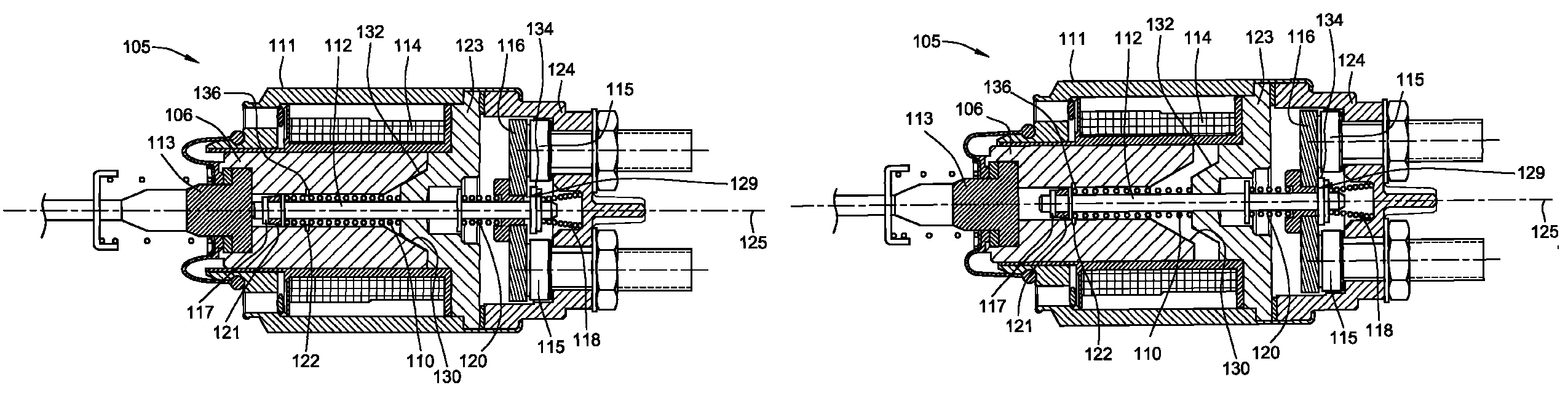
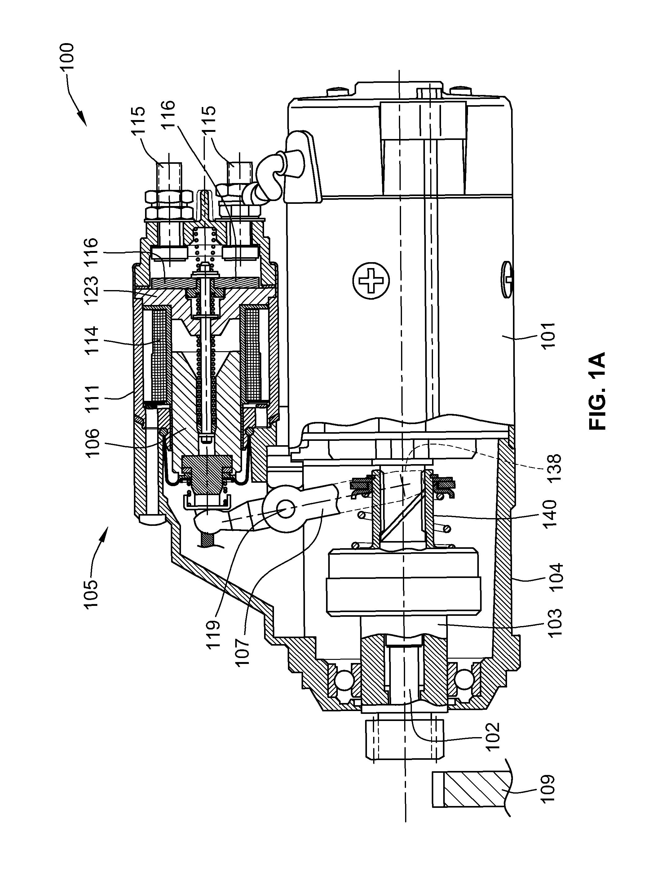
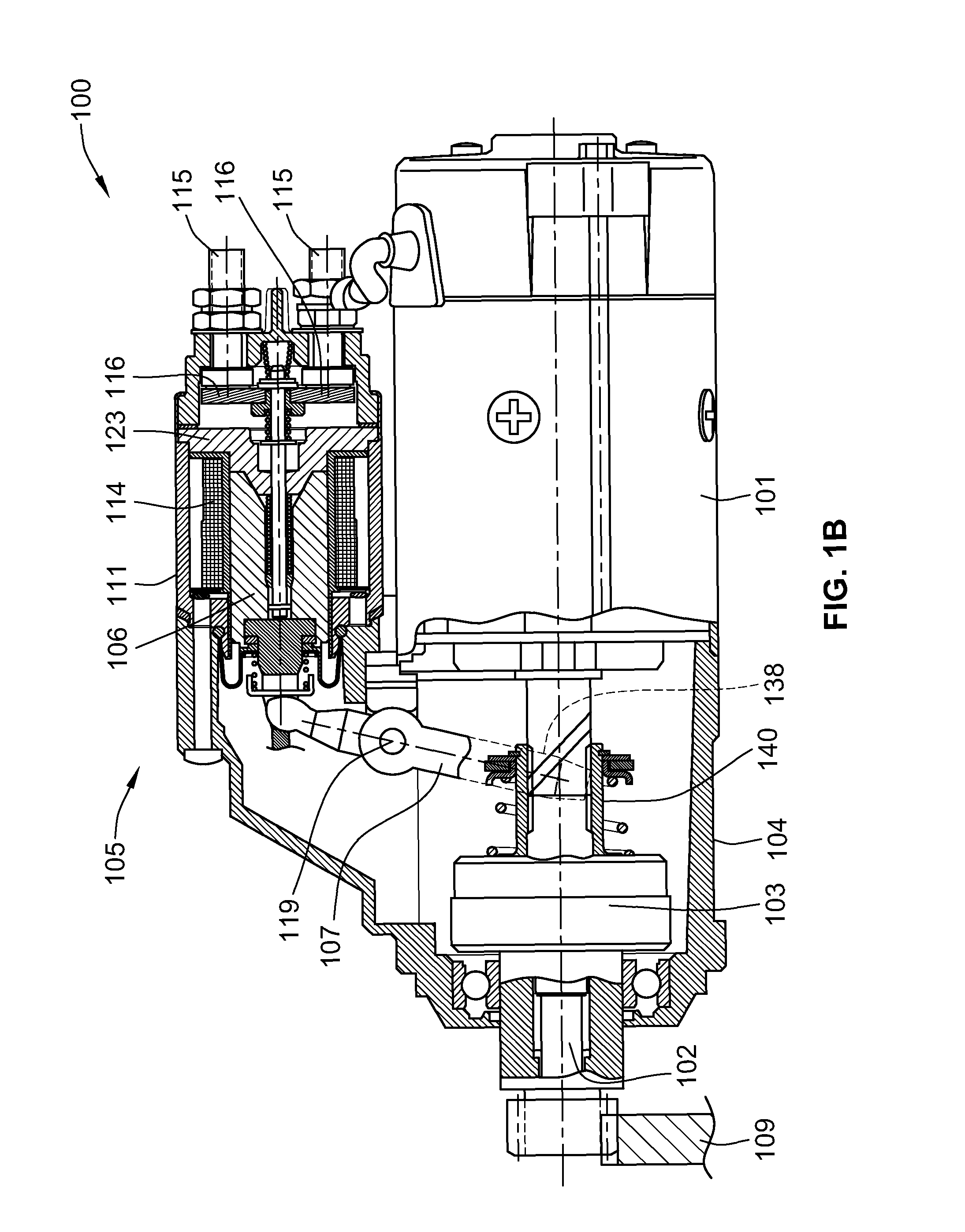
[0016]FIGS. 1A and 1B illustrate a cross-sectional view of a starter system 100 incorporating a forced return solenoid assembly 105, constructed in accordance with an embodiment of the invention. In operation, starter motor system 100 works to start the internal combustion engine (not shown), of a vehicle for example, using a DC electric motor 101 that is connected through a reduction gear (not shown) with gear shaft 102. In this embodiment, the gear shaft 102 includes a slipping clutch and pinion 103. The DC motor 101 is mounted on a front drive end bracket 104 on which is mounted to the forced return solenoid assembly 105. A plunger 106 is configured to move axially within a housing 111 of the forced return solenoid assembly 105. The axial movement of the plunger is 106 is transferred to the slipping clutch and pinion 103 through an engagement lever 107. A central portion of the engagement lever 107 is coupled to a pin 119, such that the engagement lever 107 is configured to rotat...


PUM


Abstract

A forced return solenoid that includes an electrical winding configured to create an electromagnetic field when electrical current flows through the winding, an electrical terminal configured to be connected to a source of electrical energy, and a moveable contact plate configured to be moved into contact with the electrical terminal. Embodiment of the forced return solenoid include a plunger configured to move axially in response to the electromagnetic field generated by the electrical winding. Movement of the plunger in one direction causes the moveable contact plate to connect with the electrical terminal. Movement of the plunger in the opposite direction causes an impact intended to break the connection between the moveable contact plate and the electrical terminal. Embodiments of the forced return solenoid further include a return spring configured to move the plunger in the second direction, wherein the impact means comprises a removable snap ring affixed to the plunger.

Description

FIELD OF THE INVENTION[0001]This invention generally relates to electrical components for a vehicle, and, more specifically, to starter motors used in the ignition system of a vehicle.BACKGROUND OF THE INVENTION[0002]Generally, internal combustion engines require the pistons to be moving before ignition can commence. Typically, this means that the engine must be set in motion by some external force before the engine can power itself via combustion of fuel. Most vehicles employ an electric starter to set the engine in motion, thereby allowing ignition to take place.[0003]An electric starter motor is often used to crank internal combustion engines prior to ignition. Typically, the electric starter consists of three main assemblies: 1) the solenoid switch that ensures axial movement of the plunger within the electrical coils of the switch, and, therefore, the subsequent engagement and disengagement of a pinion into a ring gear through an engagement lever, and also establishing and brea...

Claims


Application Information

Patent Timeline
Patent Type & Authority Patents(United States)
IPC IPC(8): H01H67/02
CPCH01H3/001H01H51/065
Inventor COTI{HACEK OVER (C)} IVANBRATU{HACEK OVER (S)} TOMA{HACEK OVER (Z)}KOBAL SEBASTJAN
Owner ISKRA AVTOELEKTRIKA D D
Why Eureka
Try Eureka