

Wireless communication apparatus
a communication apparatus and wireless technology, applied in the direction of orthogonal multiplex, multiplex communication, duplex signal operation, etc., can solve the problems of plurality of channels decoding, complex processing, and inability to improve transmission characteristics, so as to achieve the effect of improving transmission characteristics
- Summary
- Abstract
- Description
- Claims
- Application Information
AI Technical Summary
Benefits of technology
Problems solved by technology
Method used
Image

Examples
first embodiment
(A. First Embodiment)
[0043](A-1. Configuration of Mobile Communication System)
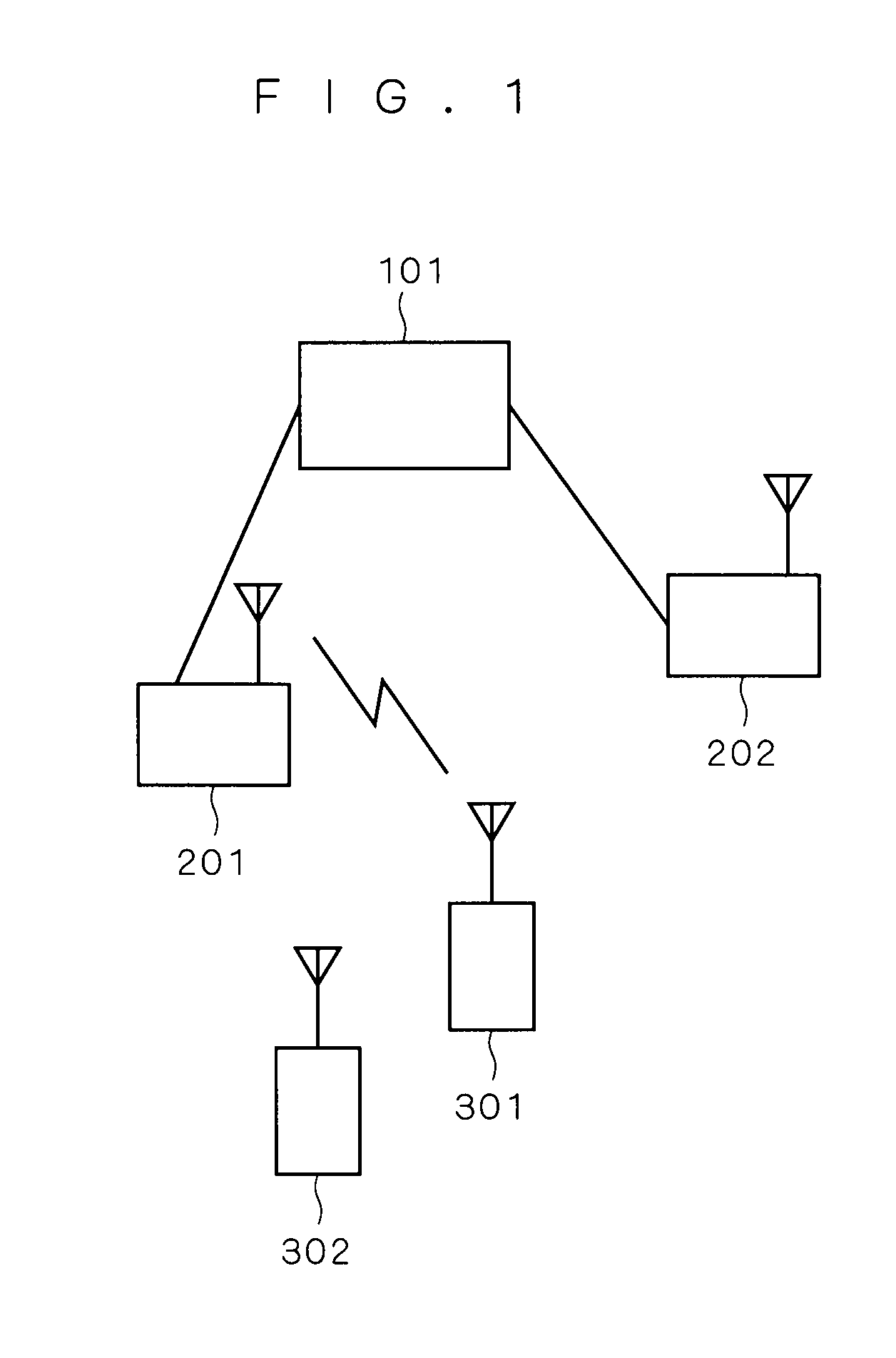
[0044]FIG. 1 is a conceptual view explaining a configuration of a general mobile communication system. In FIG. 1, a base station higher-level device 101 is connected to base stations 201 and 202 through a communication line such as ATM (Asynchronous Transfer Mode) and an IP (Internet Protocol) network, and the base station higher-level device 101 performs processing such as a gateway function with a public telephone line network and resource management across the base stations.
[0045]In the base stations 201 and 202, the mobile devices 301 and 302 and OFDMA (Orthogonal Frequency Division Multiple Access) are utilized in downstream communication (communication from the base station to the mobile device), and the mobile devices 301 and 302 and SC-FDMA (Single Carrier Frequency Division Multiple Access) are utilized in upstream communication (communication from the mobile device to the base station).
[0046](A-2...
second embodiment
(B. Second Embodiment)
[0164](B-1. Configuration of Wireless Communication Device)
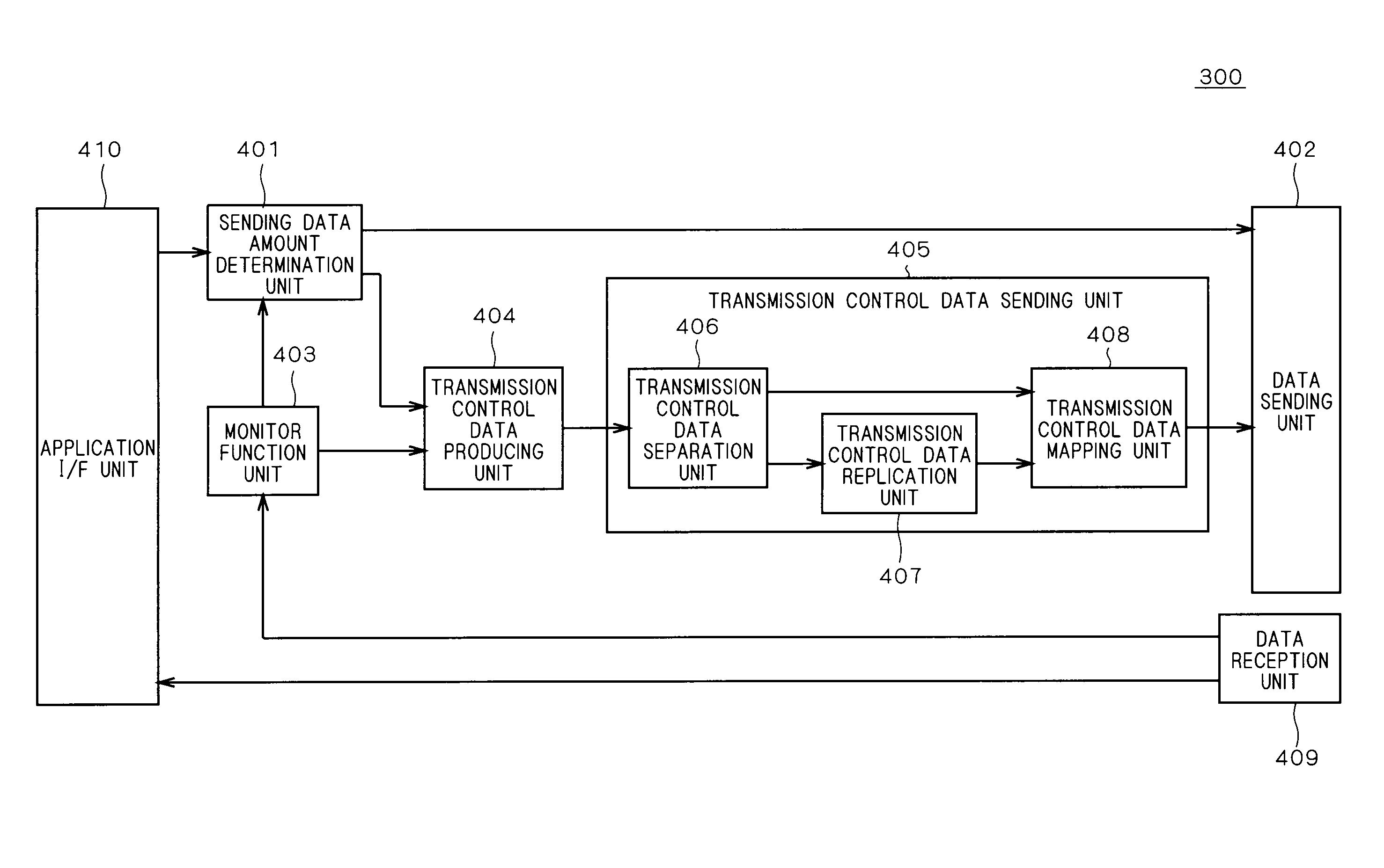
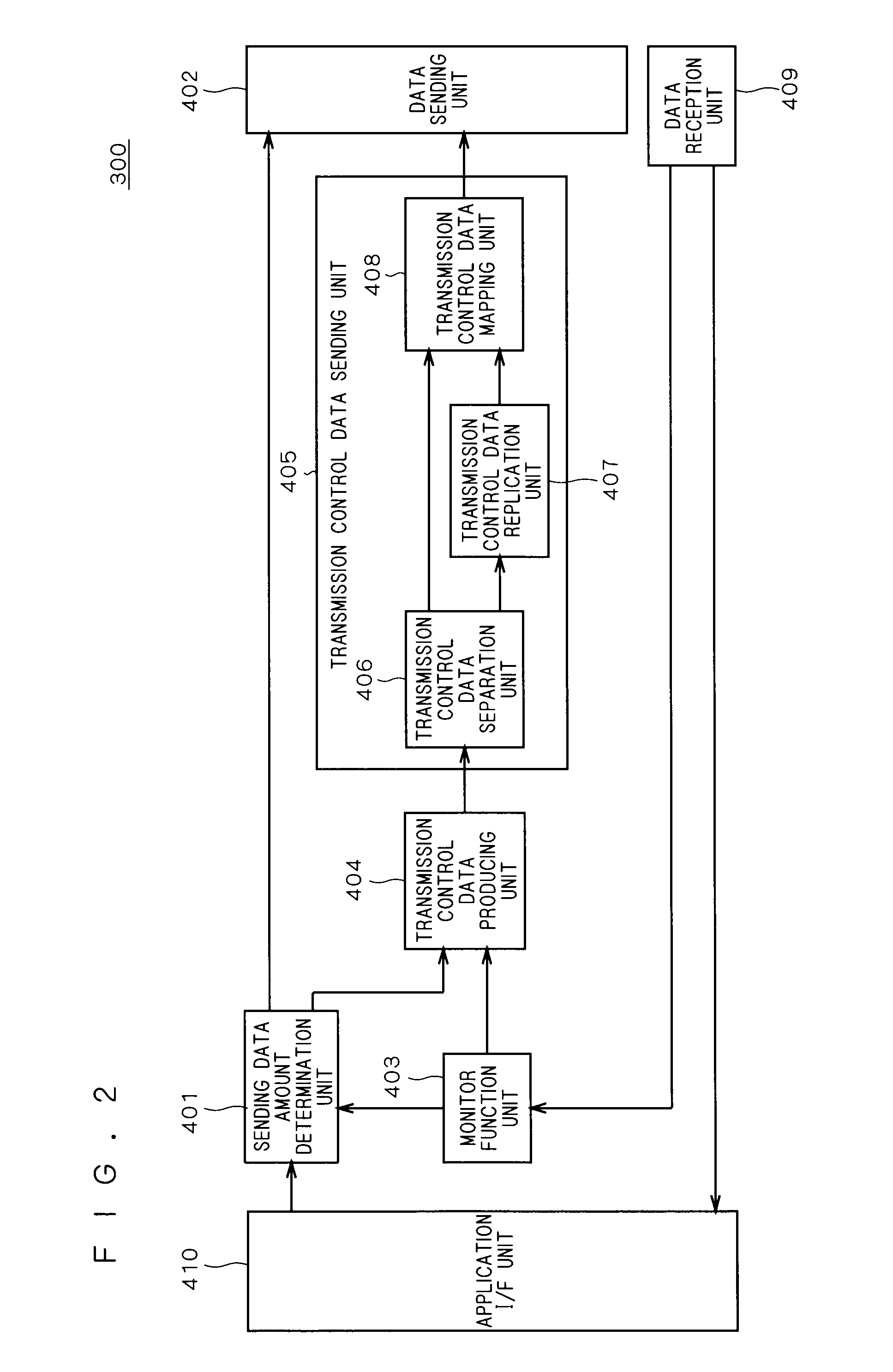
[0165]FIG. 9 is a block diagram showing a configuration of a sending unit of a wireless communication device 300A constituting the base station and mobile device in a wireless communication device according to a second embodiment of the present invention. Because the base station and the mobile device basically have the same function, only the mobile device is described below.
[0166]The wireless communication device 300A of FIG. 9 includes a transmission control data sending unit 405A instead of the transmission control data sending unit 405 in the wireless communication device 300 of FIG. 2. The same configuration as the transmission control data sending unit 405 of FIG. 1 is designated by the same numeral, and the redundant description is omitted.
[0167]The transmission control data sending unit 405A includes the transmission control data separation unit 406, an error correction unit 411, a puncture uni...
third embodiment
(C. Third Embodiment)
[0208](C-1. Outline)
[0209]A wireless communication device according to a third embodiment of the present invention in which data can efficiently be transmitted even if data sending is not performed for a long time will be described below.
[0210]In the case where the data is demodulated by a wireless communication device on the reception side, a wireless communication device on the sending side estimates what change is happened in a wireless propagation channel by receiving known data (known series) of “0” or “1”. Sometimes the known series is expressed by a replica signal, a reference signal, a pilot signal, a sync word, and a preamble.
[0211]Examples of propagation channel estimation include a method for performing the estimation by detecting the reception timing (data leading-end detection in modulation symbol units by known-series pattern and higher-accuracy data leading-end detection in which Nyquist is detected by selecting the most probable one while oversam...
PUM
 Abstract
Description
Claims
Application Information