Constant force control methodology for shock absorption

a technology of shock energy absorption and constant force, which is applied in the direction of shock absorbers, cycle equipment, instruments, etc., can solve the problems of extreme vertical shock load, particularly in the direction of rotorcraft, spinal, pelvic and other injuries of cat occupants, etc., and achieve the effect of preventing vehicle occupant injuries

Inactive Publication Date: 2012-11-13
INNOVITAL LLC +1
View PDF5 Cites 7 Cited by
  • Summary
  • Abstract
  • Description
  • Claims
  • Application Information

AI Technical Summary

Benefits of technology

[0008]It is an object of the present invention to prevent vehicle occupant injury and / or protect critical electronic / devices during shock events.
[0009]It is another object of the present invention to minimize the shock induced load experienced by the occupant / payload by utilizing the full or desired stroke of the energy absorption system.

Problems solved by technology

The minimization of shock load-induced injury is a critical issue in seat suspension design.
Scat occupants can suffer spinal, pelvic and other injuries as a result of harsh vertical / crash landings of aircraft, a problem to which rotorcraft are particularly susceptible.
Extreme vertical shock loads are also experienced by land and marine vehicles during high speed operations and in harsh environmental conditions.
In addition, such shock absorber system can isolate occupants from harmful operational vibrations, mitigate severe and repetitive operational impact shocks, and protect vital devices and electronics.
Conventional passive shock mitigation approaches are limited by their inability to adapt to varying shock levels or payload (occupant) weights.
More specifically, passive suspension systems may be tuned for a maximum expected shock amplitude and / or the heaviest expected occupant weight but would provide far from optimal results for smaller payloads and / or in lower amplitude shock conditions.
In such a case, the load transmitted to the payload via the shock absorber would be unnecessarily high (causing an unnecessary risk of injury) and the full dissipative capability of the entire absorber stroke would not be used.
Alternatively, if the passive suspension system were tuned for lower amplitude shock and / or a lower payload (occupant) weight, the suspension would be too “soft” for a heavier payload or higher amplitude shock condition, more often resulting in the absorber meeting is stroke end-stop (i.e. bottoming out), again causing an unnecessary risk of injury.

Method used


Image

  • Constant force control methodology for shock absorption
  • Constant force control methodology for shock absorption
  • Constant force control methodology for shock absorption

Examples


Embodiment Construction

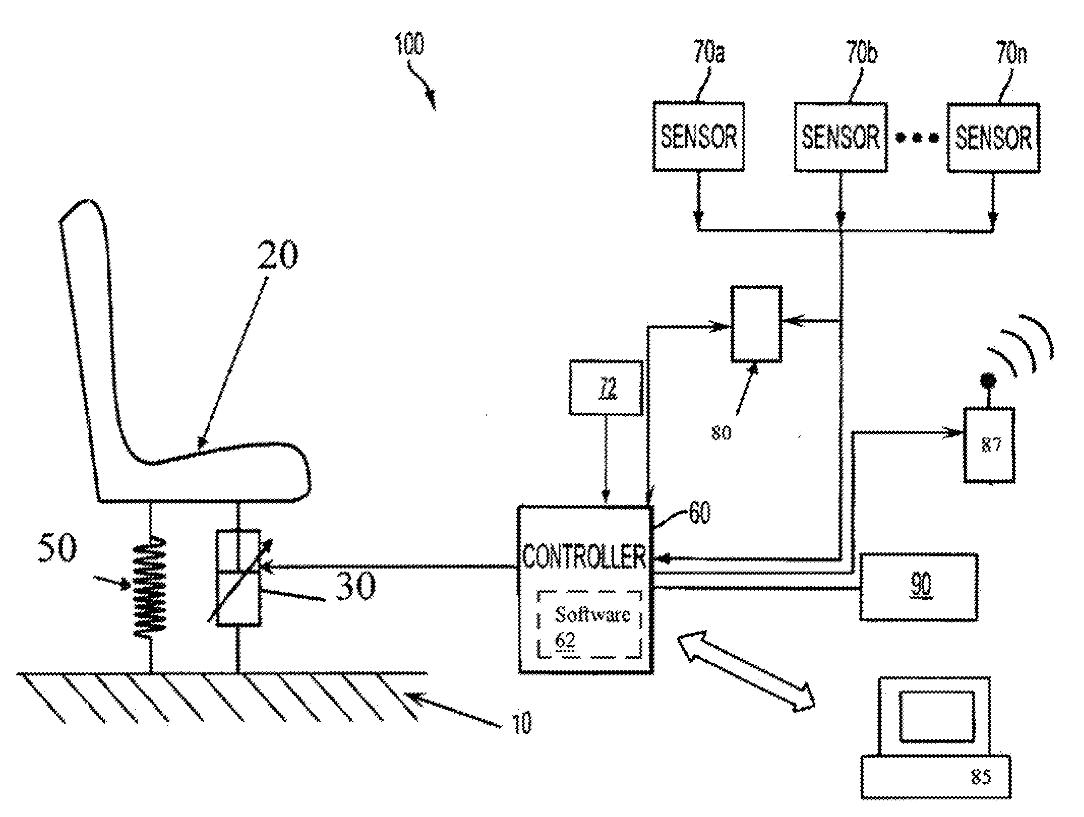
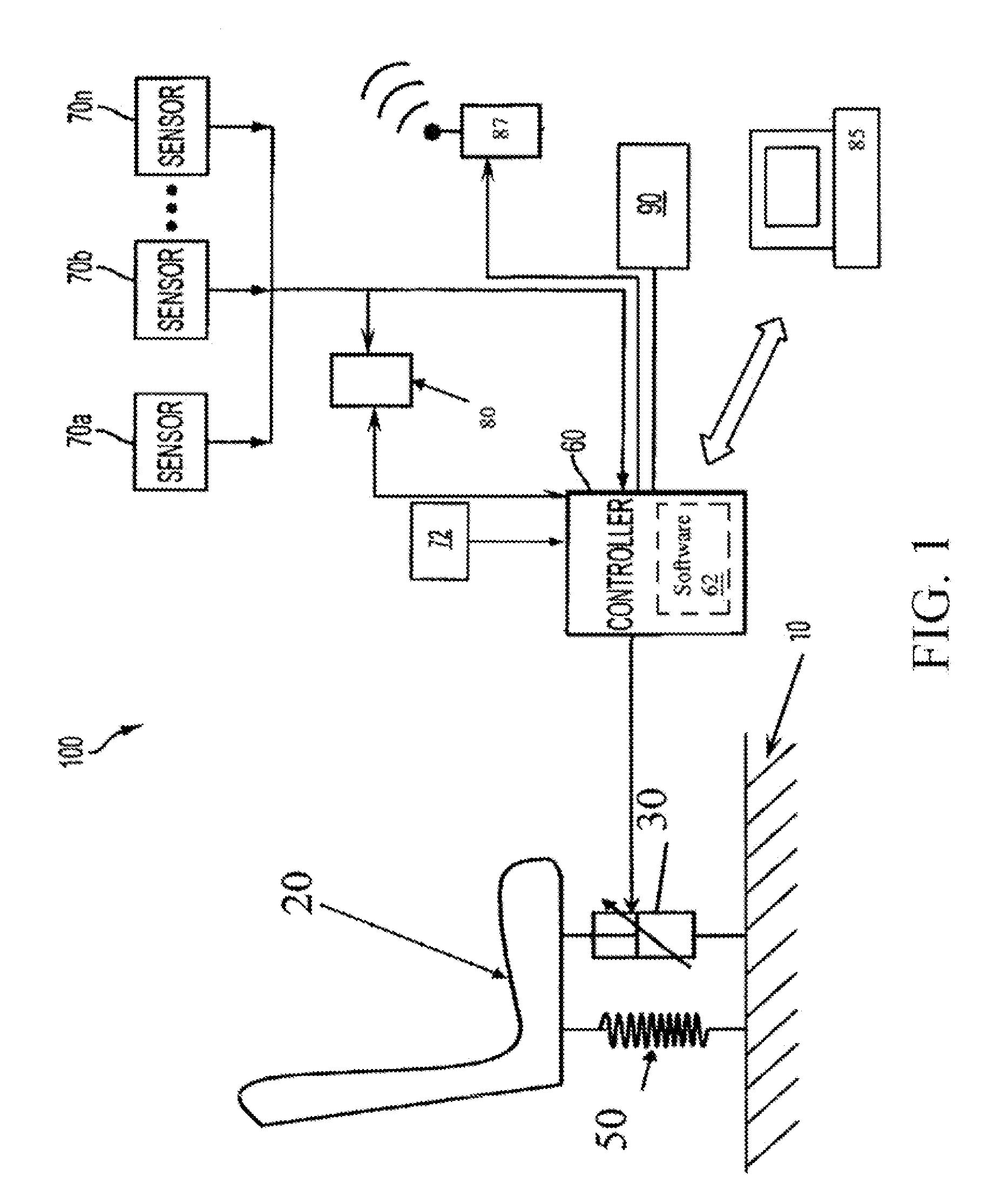
[0024]The control system according to the present invention will be herein shown in the context of a shock energy absorption system for a vehicle seat, although the invention is applicable to any payload shock energy minimization application. In the vehicle seat context, the control system includes a plurality of vehicle-mounted components including a controller (processor with memory), a sensor (e.g. displacement, velocity, accelerometer, altimeter, proximity etc.) connected to the processor to determine the impact velocity of the vehicle, and an adaptive energy absorber (EA) operatively connected between the vehicle seat and vehicle frame.

[0025]EA is herein defined as any suitable device used to absorb energy by providing a resistive force applied over a deformation distance without significant elastic rebound. EAs damp applied forces but do not store them to any significant degree (as do coil springs). EAs include fixed profile energy absorbers (FPEAs) which have a constant load-...


PUM


Abstract

A Constant Force Control methodology and system utilizing integrated sensors and unique control algorithms to determine required applied force to mitigate shock events in an adaptive energy absorption system, typically comprising of a spring and an adjustable energy absorber or damper element. By utilizing an expected acceleration profile and event duration for an anticipated shock event an acceleration amplitude can be determined from a measure impact velocity. From this and a measured payload mass a system controller can determine the force necessary to be applied by the energy absorber in order to stop the payload over the full desired length of the available energy absorber stroke in order to minimize the forces experienced by the payload.

Description

CROSS-REFERENCE TO RELATED APPLICATION(S)[0001]The present application derives priority from U.S. provisional application Ser. No. 61 / 335,469 filed 7 Jan. 2010, and is a continuation-in-part of application Ser. No. 11 / 819,875, filed Jun. 29, 2007 now U.S. Pat. No 7,878,312, and is a continuation-in-part of application Ser. No. 11 / 670,773 filed Feb. 2, 2007 now U.S. Pat. No. 7,822,522, and is a continuation-in-part of application Ser. No. 11 / 670,761, filed Feb. 2, 2007 now U.S. Pat. No. 7,921,973.BACKGROUND OF THE INVENTION[0002]1. Field of the Invention[0003]The present invention relates to a method of controlling a shock energy absorption system to minimize instantaneous payload acceleration. More particularly, the invention is a system and method for determining and applying with an energy absorption system the required constant oppositional force to achieve optimal energy dissipation over the full or partial stroke of an absorber so as to minimize the instantaneous load on the pa...

Claims


Application Information

Patent Timeline
Patent Type & Authority Patents(United States)
IPC IPC(8): B60G17/018
CPCB60N2/4242B60N2/42736B60N2/501B60N2/522B60N2/544F16F9/53F16F15/002
Inventor WANG, GANGWERELEY, NORMANHIEMENZ, GREGORYCHOI, YOUNG-TAI
Owner INNOVITAL LLC
Why Eureka
Try Eureka