Wireless sensor node architecture with autonomous streaming

a sensor node and streaming technology, applied in the field of wireless sensor node architecture with autonomous streaming, can solve the problems of inability to predict requests, important power consumption, and inability to meet the needs of users, so as to improve the sensor architecture and alleviate or prevent the mentioned drawbacks

Active Publication Date: 2012-11-13
KONINKLIJKE PHILIPS ELECTRONICS NV
View PDF0 Cites 3 Cited by
  • Summary
  • Abstract
  • Description
  • Claims
  • Application Information

AI Technical Summary

Benefits of technology

[0010]An object of the present invention is to provide an improved sensor architecture and sensing method, which alleviate or prevent the mentioned drawbacks by exploiting the characteristics of the data flow between the components in wireless sensor nodes.
[0011]Accordingly, an “autonomous” data transfer mechanism can be provided, which avoids the use of a CPU or DMA device and therefore offers minimum power consumption. Moreover, an autonomous wake-up and / or sleep-down mechanism can be implemented, where the CPU is not involved at all and, thereby, programming complexity is relieved as well. By introducing autonomous streaming modules that will have a simple and uniform programmer interface (e.g. open, close, read, write, input / output control), software (driver) portability is facilitated and automatic system generation is possible. The proposed system architecture which is based on autonomous streaming modules thus provides an energy-efficient wireless sensor node integration. The autonomous streaming modules can be built from subsystems or components that are encapsulated in the smart-shells which detect pre-specified internal events or events from the streaming data and control the activity of the subsystem or component. The streaming paradigm allows the subsystems to communicate with each other with the lowest possible overhead, thereby improving the system-level power efficiency. In addition to this, the proposed solution enhances system-level performance predictability, reduces programming complexity and exhibits better hardware scalability.
[0012]The control unit may be adapted to control the operational mode of the component or subsystem based on internal events generated by a timer, so that time-dependent control of the operation mode or operation state of the subsystem or component is possible.
[0014]The smart shell may comprise the control unit, a stream communication port adapted to generate said external events based on stream content, and a local manager adapted to interpret the generated external events. This modular and autonomous topology enables energy-efficient operation of the sensor node. In a specific example, the local manager may comprise an operation controller for controlling the operation mode based on at least one of detected events and status of said component or subsystem.

Problems solved by technology

Power consumption is an important issue in most wireless sensor network applications.
If the nodes are used in biomedical monitoring they need to operate reliably, even with unpredictable hardware behavior.
Although the use of DMA is more energy efficient than a CPU in moving data, there are a number of drawbacks associated with both approaches.
First, lack of predictability arises from the fact that the CPU and the DMA device are shared devices that operate on an interrupt basis which makes them intrinsically non-predictable in the sense that service requests could be missed.
Such lack of predictability could even lead to non-real time response to critical events which for real-time alert applications is not acceptable.
Second, a transfer overhead is generated from the point of view of data transport between components, a CPU or DMA device with its accompanying operation protocol introduces an overhead that essentially reduces energy efficiency.
Third, lack of hardware scalability arises from the fact that the DMA device is a central shared resource which is not easily scalable when a sensor node needs to change operational mode with distinctly different performance requirements and / or handles multiple data streams originating from multiple sensor units, primarily due to the limited number of DMA channels.
Fourth, programming complexity results from the fact that from application programmer point of view, (re-)configuring the DMA device and / or peripherals is not a simple task and could lead to non-optimal operation modes.
Unfortunately, this often requires a significant programming effort (and, therefore, is sometimes even just completely ignored) as waking-up components is non-trivial due to the intrinsic wake-up times (related to e.g. power-up and / or stabilization) that somehow need to be accounted for in the application program.

Method used


Image

  • Wireless sensor node architecture with autonomous streaming
  • Wireless sensor node architecture with autonomous streaming
  • Wireless sensor node architecture with autonomous streaming

Examples


Embodiment Construction

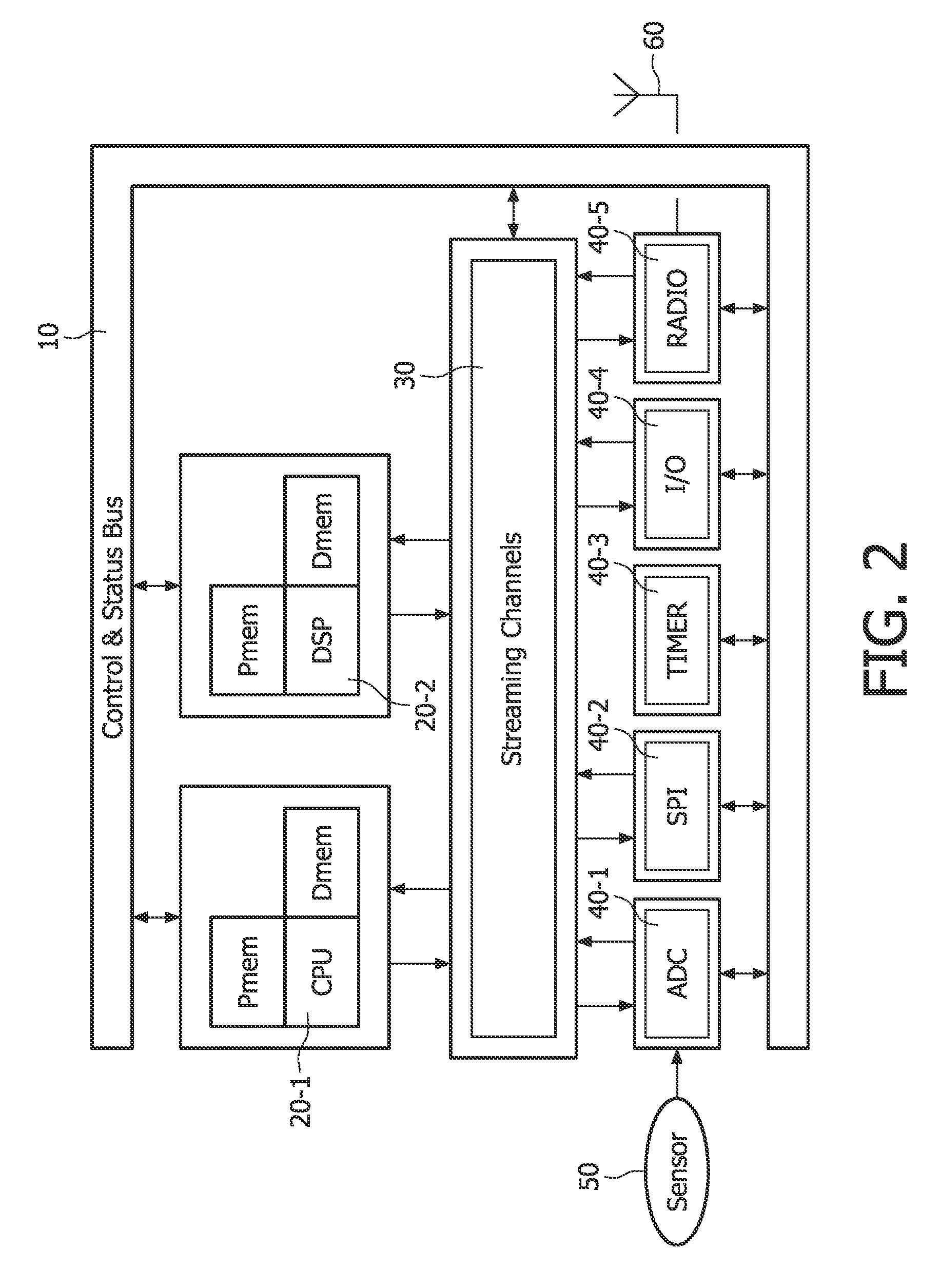
[0030]Various embodiments of the present invention will now be described based on a BSN system as an example of a wireless sensor network.

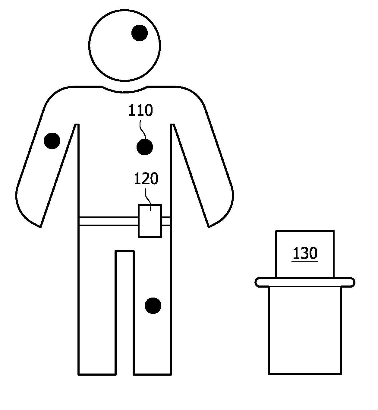
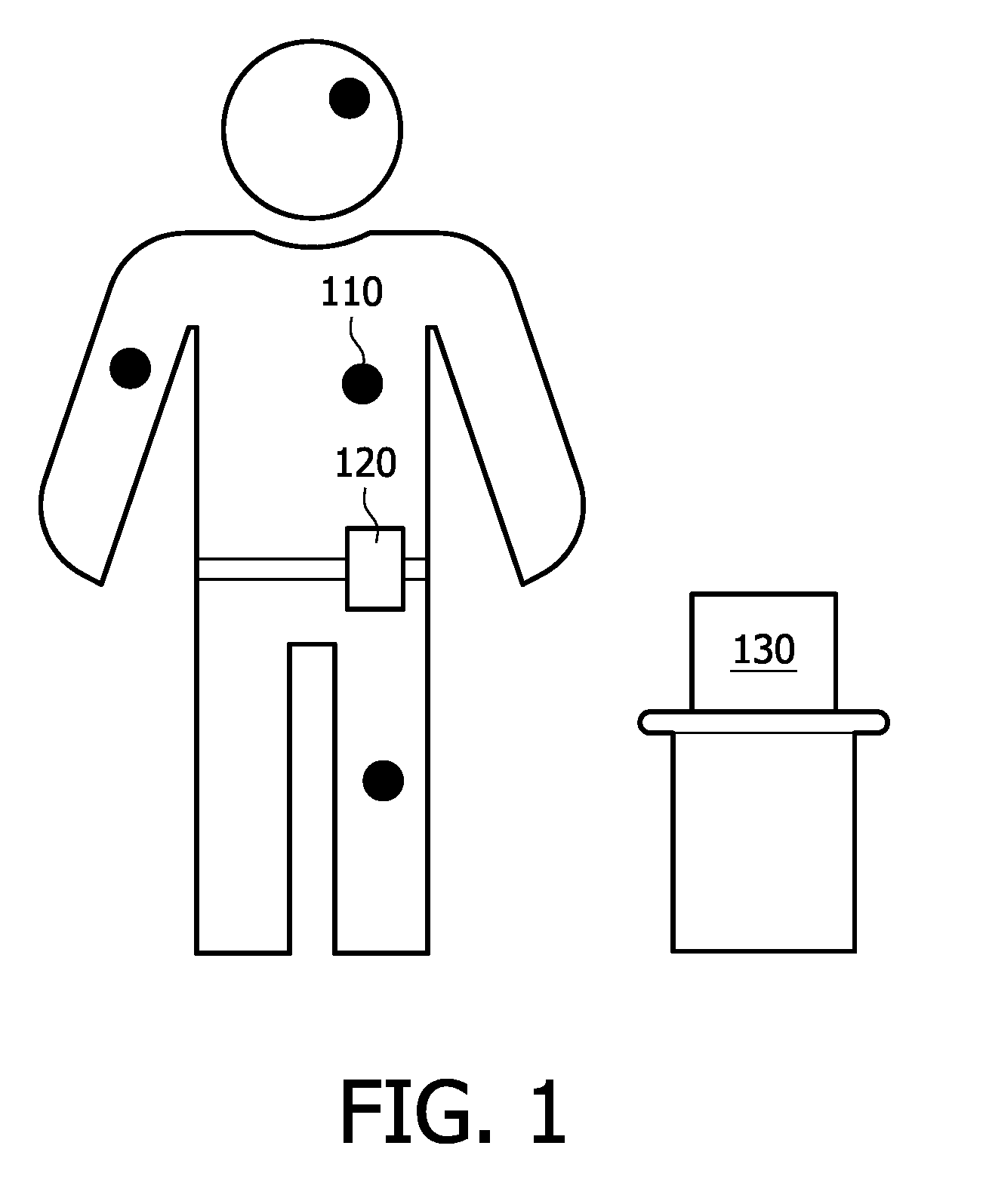
[0031]FIG. 1 shows a schematic diagram of a BSN system with a number of locations on a body, where sensor nodes or devices 110 are attached. Besides the sensor nodes 110 located around or implanted in the body, the BSN system may comprises one or more access or collating devices 120, 130, which receive signals or sensing data from the sensor nodes 110 and which may be configured to upload the received information to a central server (not shown).

[0032]In the exemplary arrangement of FIG. 1, a mobile access or collating device 120 is configured to be worn somewhere on the body (e.g. on a belt), and / or may alternatively be integrated into an electronic device, such as a mobile phone, which would be carried anyway. Additionally, a fixed access or collating device 130 may be located in specific areas (e.g. at home, for example in the lounge and bedroom...


PUM


Abstract

A sensor device includes at least one autonomous streaming module. Predetermined internal events of the autonomous streaming module or predetermined external events from streaming data at an interface to a smart shell of the autonomous streaming module are detected. An operational mode of a component or subsystem within the smart shell of the autonomous streaming module is controlled in response to the detection.

Description

FIELD OF THE INVENTION[0001]The present invention relates to a sensor device and method for collecting sensor data in sensor networks, such as—but not limited to—body sensor networks.BACKGROUND OF THE INVENTION[0002]The benefits of collecting medical information from a person over a long time period and during everyday life have long been prophesized. In recent years, many research groups have been investigating body sensor networks (BSNs). These are networks of multiple sensors or sensing devices or sensing nodes, deployed around, and even in, the body and transmitting their data over a digital radio link. Thus, each sensor should be as discrete and small as possible.[0003]A number of protocols are currently known which purport to be protocols for ‘low-power’ networks and might therefore be suitable for BSNs. Examples of such protocols are described in “Part 15.4: Wireless Medium Access Control (MAC) and Physical Layer (PHY) Specifications for Low-Rate Wireless Personal Area Networ...

Claims


Application Information

Patent Timeline
Patent Type & Authority Patents(United States)
IPC IPC(8): G06F15/16
CPCA61B5/0002A61B5/0024A61B2560/0209A61B5/0008
Inventor VAN MEERBERGEN, JOZEF LOUISABBO, ANTENEH ALEMUBENNEBROEK, MARTINUS THEODORUSSANTANA, OCTAVIOYSEBOODT, LENNART
Owner KONINKLIJKE PHILIPS ELECTRONICS NV
Why Eureka
Try Eureka