
Control apparatus for internal combustion engine

a control apparatus and internal combustion engine technology, applied in the direction of electric control, machines/engines, instruments, etc., can solve the problems of excessive in-cylinder pressure, vibration of the engine block, and metallic sound in the engine block, so as to reduce the fluctuation of torque and abnormal vibrations, reduce the effective compression ratio, and reduce the effect of effective compression ratio

Active Publication Date: 2012-11-27
MITSUBISHI ELECTRIC CORP +1
View PDF20 Cites 23 Cited by
  • Summary
  • Abstract
  • Description
  • Claims
  • Application Information

AI Technical Summary

Benefits of technology

The present invention provides a control apparatus for an internal combustion engine that can detect and suppress abnormal combustion and ignition. The control apparatus includes operating state detection means, variable valve mechanism control means, ignition timing control means, knock detection means, knock suppression means, abnormal ignition detection means, and abnormal ignition suppression means. The control apparatus can detect and suppress abnormal combustion and ignition quickly to reduce fluctuations in torque and vibrations.

Problems solved by technology

First, after spark ignition with a spark plug, a flame propagates from the spark plug.
As a result, when the end gas is self-ignited, a shock wave is generated.
It is believed that the generation of the shock wave causes an excessively high in-cylinder pressure, a vibration of an engine block, and a metallic sound in the engine block.
Even in such a case, the excessively high in-cylinder pressure, the vibration of the engine block, and the metallic sound in the engine block are sometimes caused.
If any one of the kinds of abnormal ignition occurs, the generation of an uncomfortable metallic sound or a fluctuation in engine output occurs.
In an extreme case, the engine is damaged.
However, the prior art has the following problems.
According to the conventional judgment method based on the difference in time between the ignition timing and the time of occurrence of the vibration, it is difficult to specify the time of occurrence of the vibration due to the abnormal ignition because the engine is always vibrated during the operation.
Therefore, the normal knock is frequently erroneously judged as the abnormal ignition.
Moreover, in the conventional judgment method of judging that the abnormal ignition has occurred when the vibrations due to the knock are not stopped within the predetermined period of time even after the ignition timing is corrected to the retard side, the vibrations due to the knock increase, or the vibrations due to the knock occur even after the ignition timing is retarded to the most-retarded ignition timing, there is a problem in that a torque is greatly lowered because the ignition timing is continuously retarded.
Further, the judgment is made based on the continuous occurrence of the vibrations due to the knock over the predetermined period of time, and hence the above-mentioned conventional judgment method is also disadvantageous in that the uncomfortable vibrations or metallic sounds are continuously generated until the judgment of the abnormal ignition is made.
The problem here is the case where a combustion state cannot get out of the abnormal combustion area even when the ignition timing is continuously retarded, as indicated by a dotted-line arrow (b′) illustrated in FIG. 9.
Even with the conventional knock suppressing method of lowering the effective compression ratio after retarding the ignition timing to the most-retarded position in the engine with the high compression ratio, there is a problem of a remarkable reduction of the torque because the ignition timing is first retarded to the most-retarded position, as indicated by the dotted-line arrow (b′) illustrated in FIG. 9 and as illustrated in FIGS. 10A and 10B.
Moreover, as illustrated in FIG. 9, there is a possibility that the abnormal combustion occurring in the area is not due to the knock but due to the post-ignition or the pre-ignition.
Therefore, there is another problem in that the abnormal combustion cannot be sufficiently suppressed only by reducing the effective compression ratio.

Method used


Image

  • Control apparatus for internal combustion engine
  • Control apparatus for internal combustion engine
  • Control apparatus for internal combustion engine

Examples


first embodiment

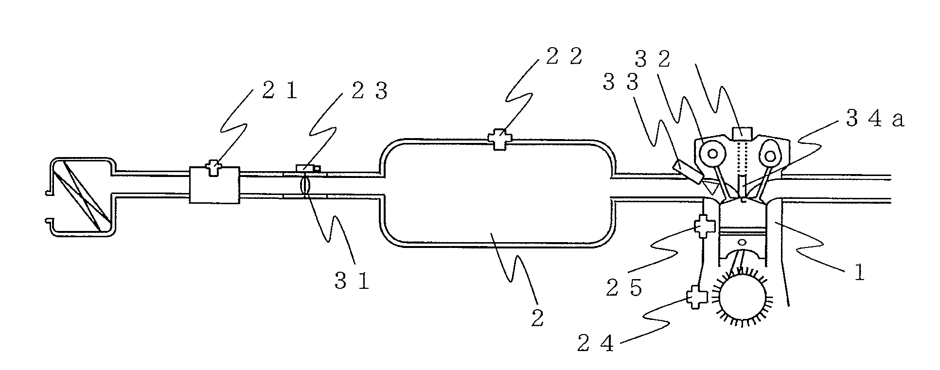
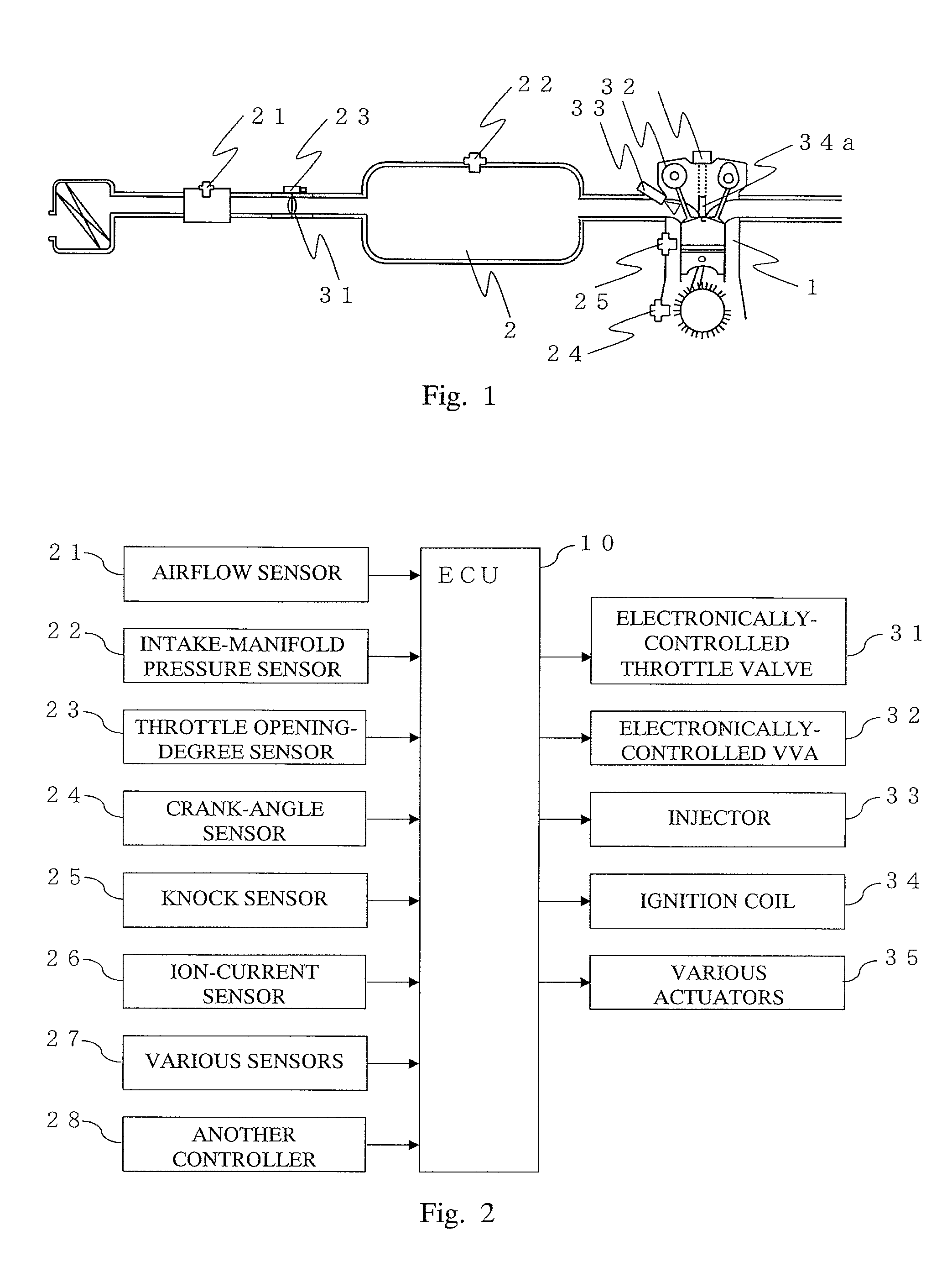
[0031]FIG. 1 is a schematic configuration diagram of the internal combustion engine in a first embodiment of the present invention. Further, FIG. 2 is a block diagram of a control apparatus for the internal combustion engine in the first embodiment of the present invention. Control of the internal combustion engine in this first embodiment is performed by an electronic control unit (hereinafter, referred to as “ECU”) 10.

[0032]Input signals respectively from an airflow sensor 21, an intake-manifold pressure sensor 22, a throttle opening-degree sensor 23, a crank-angle sensor 24, a knock sensor 25, an ion-current sensor 26, other various sensors 27 and another controller 28 are connected to the ECU 10. Moreover, to the ECU 10, an electronically-controlled throttle valve 31, an electronically-controlled variable valve attenuation (VVA; variable valve mechanism) 32, an injector 33, an ignition coil 34, and various actuators are connected as targets to be controlled (see FIG. 2).

[0033]In...


PUM


Abstract

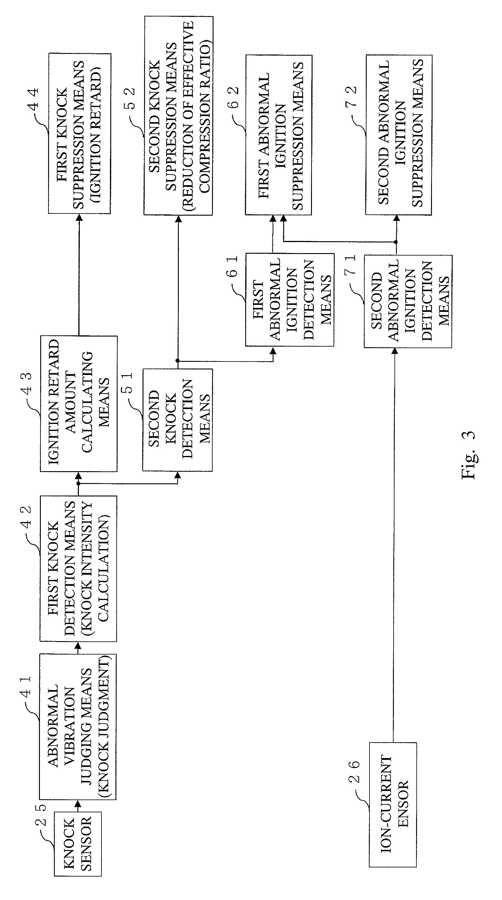
Control apparatus for an internal combustion engine including: a second knock detection unit for detecting occurrence of a second knock due to an effective compression ratio when ignition timing is on a retard side of a predetermined value in the case where a first knock is detected; a second knock suppression unit for suppressing the second knock when the second knock is detected; a first abnormal ignition detection means for detecting occurrence of first abnormal ignition due to the pre-ignition or the post-ignition when a knock intensity of the second knock is equal to or larger than a predetermined value; and a first abnormal ignition suppression unit for suppressing the first abnormal ignition by performing fuel control for the internal combustion engine when the first abnormal ignition is detected.

Description

BACKGROUND OF THE INVENTION[0001]1. Field of the Invention[0002]The present invention relates to a control apparatus for an internal combustion engine, in particular, to a control apparatus for an internal combustion engine, which detects and suppresses abnormal combustion due to a knock, pre-ignition, and post-ignition, which occurs in the internal combustion engine.[0003]2. Description of the Related Art[0004]A method of detecting a knock, which corresponds to a kind of abnormal combustion occurring in an engine, by a vibration sensor is conventionally known. It is known that, if the knock occurs while the engine is in operation, vibrations in a specific frequency band occur according to a vibration mode of the engine or that of the knock. Therefore, the conventional knock detection is performed by measuring a vibration intensity of the specific frequency.[0005]Specifically, an analog bandpass filter circuit is used to extract the specific frequency. A method of measuring the vibr...

Claims


Application Information

Patent Timeline
Patent Type & Authority Patents(United States)
IPC IPC(8): F02P5/00
CPCF02D13/0226F02D13/0269F02D15/00F02D35/027F02D37/02F02D41/0002F02P5/152F02P17/12F02D35/021F02D2041/001Y02T10/46Y02T10/142Y02T10/42Y02T10/12Y02T10/40
Inventor HAGARI, HIDEKIMAKINO, TOMOKAZUEZUMI, KEITAROKUSUNOKI, TOMOKUNI
Owner MITSUBISHI ELECTRIC CORP
Learn More