[0007]It is the primary object of this invention to provide a vibration isolator of sturdy / rugged construction for use between a fluid collection pan and a furnace, air conditioning unit, storage hot
water heater tank, or other fluid-producing or fluid-containing unit, which comprises materials and a configuration that prevent movement of the furnace / unit / tank from its originally established position relative to the fluid collection pan beneath it. A further object of this invention is to provide a vibration isolator that helps to raise a furnace / unit / tank above the
maximum depth intended for routine condensate / fluid collection in the pan, so that the furnace / unit / tank is not in constant contact with collected condensate / fluid. It is also an object of this invention to provide a vibration isolator that is configured to
resist rollover and / or popping-out when a heavy furnace / unit / tank is moved across it. A further object of this invention is to provide a vibration isolator made from materials that are strong,
impact-resistant,
heat resistant, non-flammable, impervious to
corrosion, unaffected by extreme ambient temperature fluctuations, and have resistance to buckling, bowing, warping,
distortion, and collapse during extended use. It is a further object of this invention to provide a vibration isolator that can be used to meet non-combustible clearance requirements in furnace installations. It is also an object of this invention to provide a vibration isolator providing features that increase vibration dampening, while concurrently reducing material cost.
[0008]The present invention, when properly made and used, provides a highly
impact-resistant
grommet used as a safety-enhancing vibration isolator between a heavy furnace, air conditioning unit, storage hot water heater tank, or other fluid-producing or fluid collecting unit presenting a risk of fluid damage to its surroundings and the fluid-collecting tray or pan placed under it. Raised supports with top receiving holes or indentations elevate the furnace / unit / tank, and one present invention vibration isolator per hole / indentation collectively provides
weight distribution management for the pan and reduces the opportunity for the furnace / unit / tank to move relative to the pan, thereby preventing premature pan failure and / or collapse. The present invention vibration isolators can comprise high-temperature resistant materials, provide enhanced heat deflection around a supported furnace / unit, and can be sized to meet non-combustible clearance requirements in furnace applications. The present invention vibration isolators also each have a generally
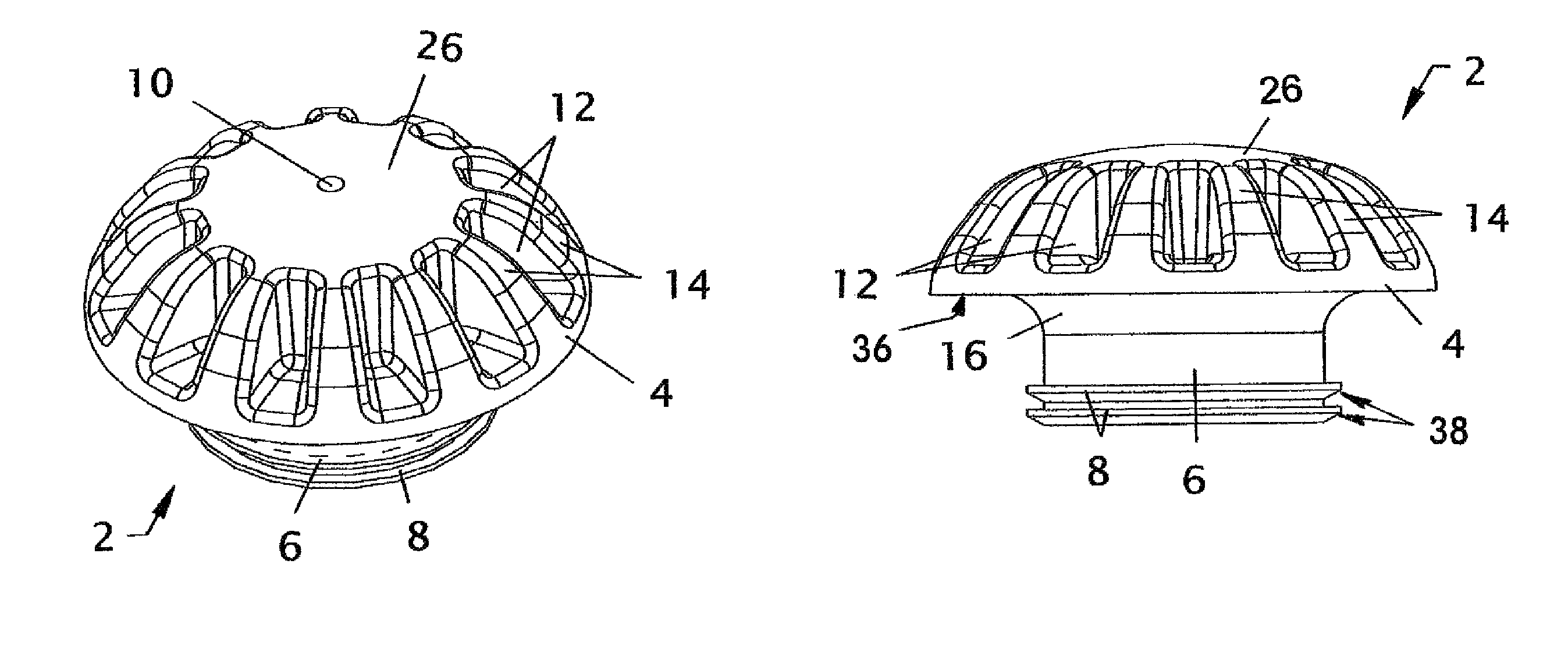
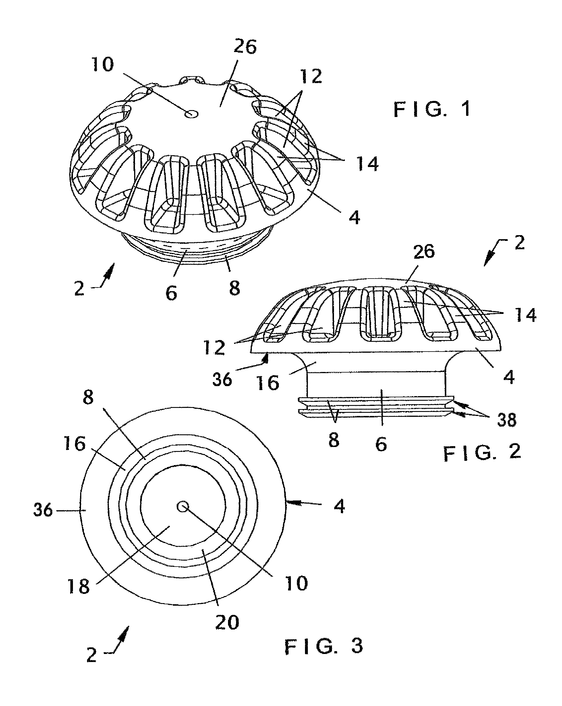
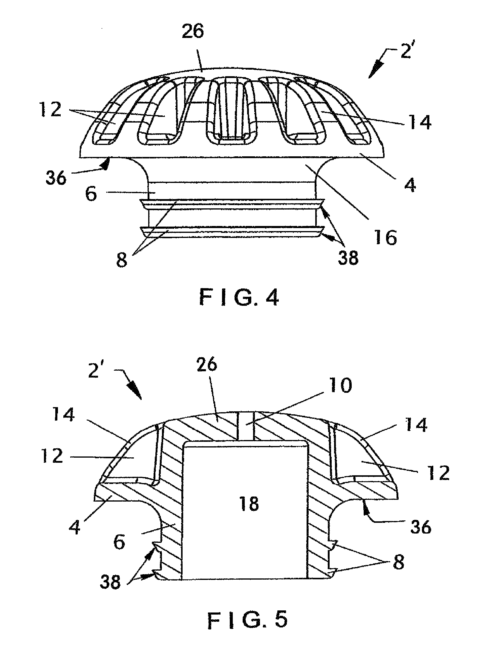
mushroom-shaped cap with a flat or slightly convex top area that is in contact with the heavy furnace or fluid-producing unit during its use, a central opening in the top area of the cap that communicates with a hollow interior area, and multiple spaced-apart ribs each separated by a cutout area on the cap's exterior surface and radially extending from the top area and fully around it. As the number of ribs increases on each present invention vibration isolator without diminishing the caps material strength, in addition to a reduction in material cost, the caps vibration isolating capability is enhanced. Each present invention vibration isolator also has a substantially cylindrical stem depending downwardly from its broad cap and a central bore communicating with the central opening of the cap. The substantially cylindrical stem also has at least one (but preferably two) spaced-apart, wedge-shaped, removal-resisting projection outwardly extending from the bottom part of its exterior surface that during use is in contact with a receiving hole or indentation in a fluid collection pan positioned under the furnace, tank, or fluid-producing unit. The top surface area in the cap, multiple radially-extending ribs, flared connection between cap and stem, and at least one wedge-shaped projection on its stem, all work together to
resist rollover when a heavy furnace of air conditioning unit is moved across the present invention vibration isolators, which allow each one to haveretain an optimal configuration and be in an optimal orientation to collectively provide safety-enhancing contact between the support surfaces of the pan and the bottom surface of the supported fluid-causing unit for
weight distribution management that reduces the opportunity for movement of supported furnace / tank / unit relative to the pan, thereby lessening the likelihood of premature pan collapse. In addition, the tapering connection of the present invention cap and stem, where cap material runs partially down the stem, provides a non-angular surface that conforms to the top edge of the receiving hole or indentation into which it is placed also assists in
rollover prevention.
