Fuel cell comprising oxygen electrode with surface nanostructure

a fuel cell and surface nanostructure technology, applied in the field of fuel cells, can solve the problems of not being able to apply similar immobilizing treatment to the numerous platinum nanoparticles, and not being able to achieve the desired immobilizing effect, etc., to achieve uniform reaction rate and precise operation

Active Publication Date: 2012-11-27
PANASONIC CORP
View PDF15 Cites 1 Cited by
  • Summary
  • Abstract
  • Description
  • Claims
  • Application Information

AI Technical Summary

Benefits of technology

[0029]According to the fuel cell of the present invention, improved and stable power generation performance will be realized without reducing reactive area in the catalyst.

Problems solved by technology

According to the foregoing conventional methodologies, since the platinum nanoparticles were completely embedded below carbon overlayers at the earlier stage, any reactive element (oxygen, hydrogen) is not capable of being accessed to the surface thereof to lose any catalytic function.
Thus, it is substantially impossible to apply similar immobilizing treatment to the numerous platinum nanoparticles, any desired immobilizing effect would not be realized thereby.
When chemical bonding force based on molecular cross-linked structure was employed to immobilize the catalyst nanoparticles, there are problems both of significantly changing the surface property of the catalyst nanoparticles with chemical bonding and of significantly reducing the surface area with catalytic activity.

Method used


Image

  • Fuel cell comprising oxygen electrode with surface nanostructure
  • Fuel cell comprising oxygen electrode with surface nanostructure
  • Fuel cell comprising oxygen electrode with surface nanostructure

Examples


embodiments

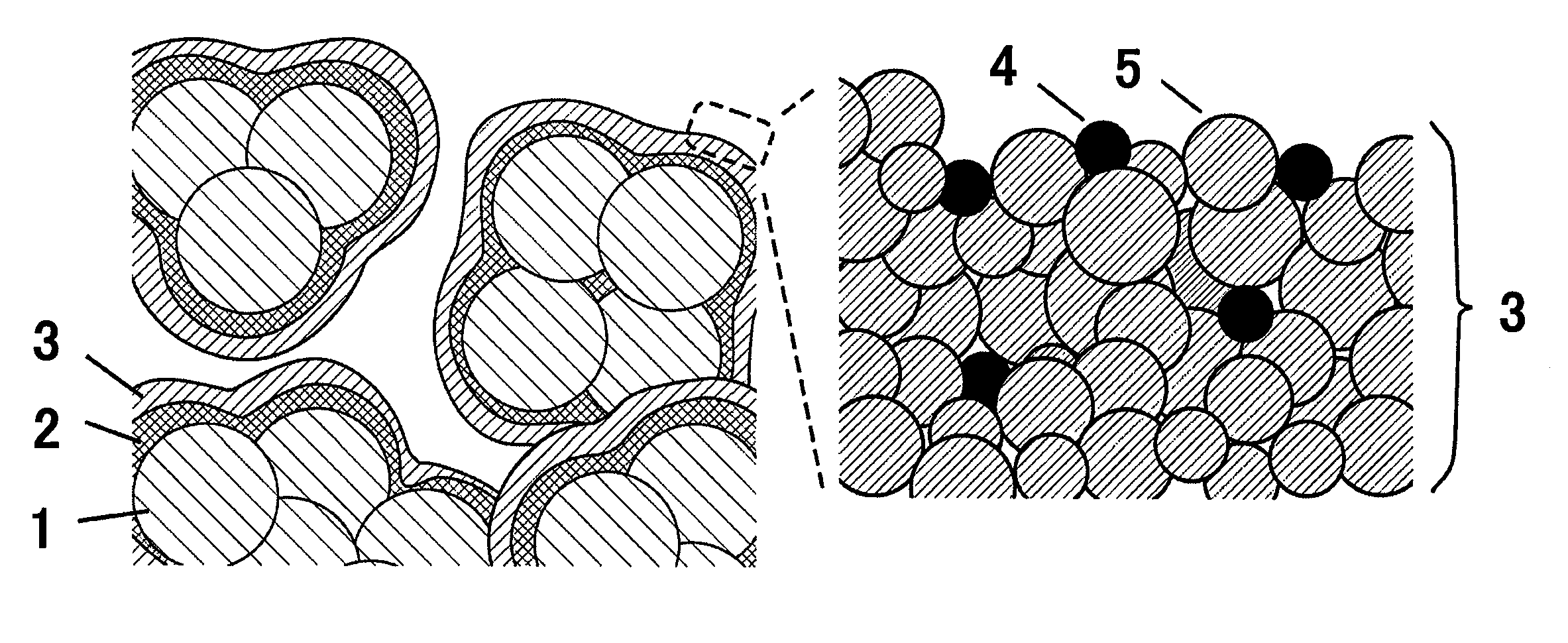
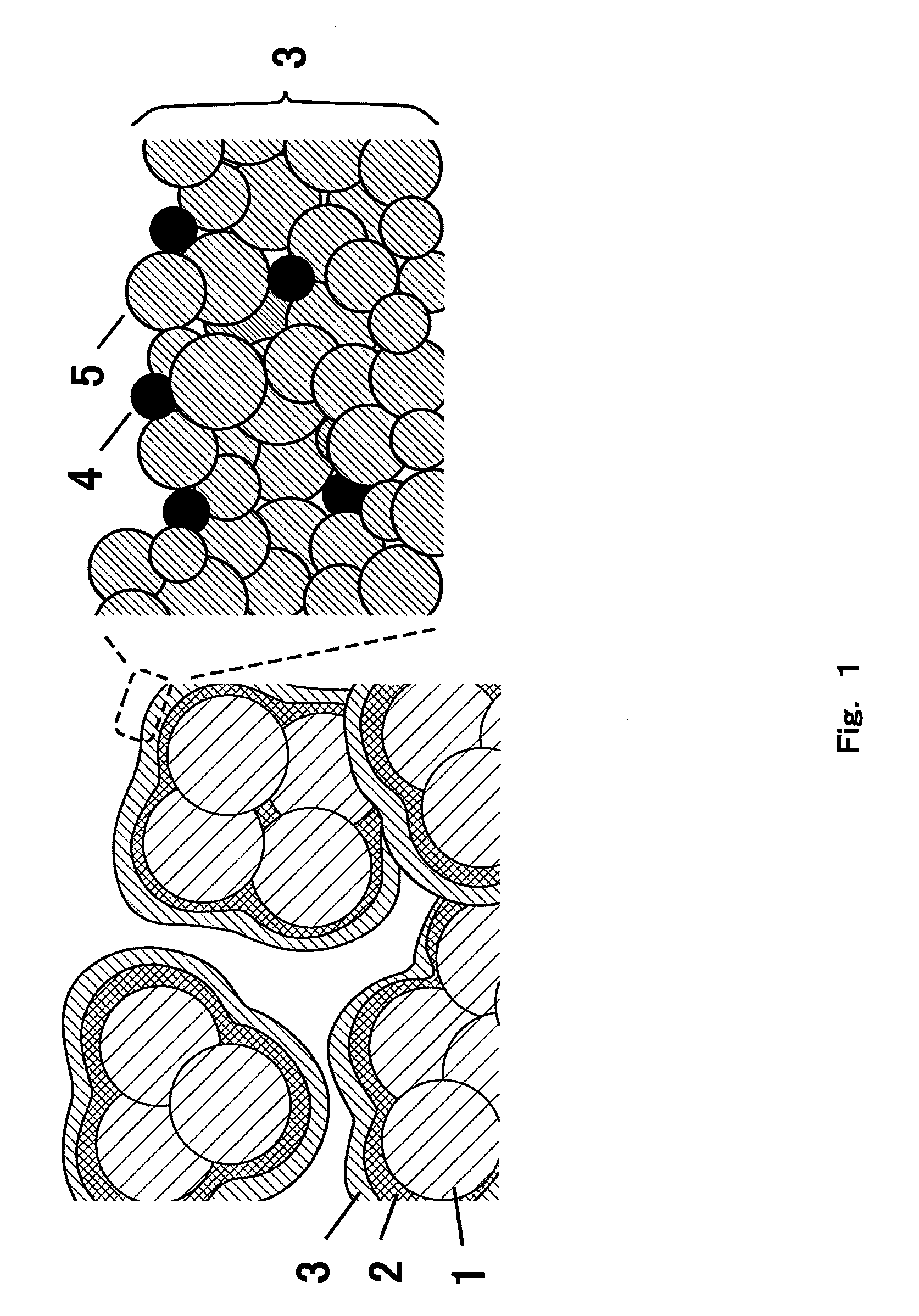
[0042]FIG. 1 is a cross-sectional view of the oxygen electrode (a catalytic electrode) with surface nanostructure according to Embodiment 1. In FIG. 1, 1 indicates the carbon particles of conductive powder, 2 indicates the carbon thin-film of conductive thin-film, and 3 indicates the surface nanostructure. Carbon particles 1 are bonded to one another with the carbon thin-film 2, and the surface nanostructure 3 is formed on the surface of the carbon thin-film 2. Such constitutive elements increase the surface nanostructure 3 per unit volume of the oxygen electrode.

[0043]Surface nanostructure 3 formed on the carbon thin-film 2 further comprises the catalyst nanoparticles 4 and the carbon nanoparticles 5. Right column of FIG. 1 is the enlarged view of the outermost of the surface nanostructure 3. Quasi-spherical carbon nanoparticles 5 form three-dimensional structure where the catalyst nanoparticles 4 are confined at vacancies and recess. This surface structure has pathways to surface ...

example 1

Production of Oxygen Electrode

[0054]Oxygen electrode was produced by bonding acetylene black of the carbon particles 1 with the carbon thin-film produced by heat-treating macromolecule as the carbon thin-film 2 and forming on their surface the surface nanostructure 3 as shown in Reference Example.

[0055]Then, 4.0 g of acetylene black (DENKI KAGAKU KOGYO KABUSHIKI KAIHSA) with a diameter of about 50 nm, 2.0 g of polyacrylonitrile (Sigma-Aldrich Corporation) and 54.6 g of dimethylacetamide (Wako Pure Chemical Industries, Ltd.) were mixed and the mixture was agitated for 20 hours with a ball mill. 1.69 g of this mixture was dropped on 19.6 cm2 of carbon paper (Toray), and the solvent was evaporated in the low-vacuum chamber. Then the carbon paper was heated with the low-vacuum dryer. Temperature was elevated from the room temperature to 120° C. in 40 minutes and the elevated temperature was kept for 2 hours. Finally, this carbon paper was transferred to an infrared imaging furnace under...


PUM

PropertyMeasurementUnit
diameteraaaaaaaaaa
diameteraaaaaaaaaa
diameteraaaaaaaaaa

Abstract

An oxygen electrode used in the fuel cell and includes a plurality of carbon particles, a carbon thin-film, and surface nanostructure. The carbon particles are bonded to one another with the carbon thin-film, and the surface nanostructure is formed on the surface of the carbon thin-film. The surface nanostructure comprises catalyst nanoparticles made of platinum (Pt) and carbon nanoparticles. According to this combination of these elements, the catalyst nanoparticles are confined within three-dimensional structure to be formed by the carbon nanoparticles and are immobilized without losing space which allows any reactant to be accessed to the surface of the catalyst nanoparticles.

Description

RELATED APPLICATIONS[0001]This application is a Continuation of U.S. application Ser. No. 12 / 652,468, filed on Jan. 5, 2010, now abandoned, which is a continuation application under U.S.C. 111(a) of pending prior International application No. PCT / JP2009 / 001319, filed on Mar. 25, 2009, which in turn claims the benefit of Japanese Application No. 2008-104424 filed on Apr. 14, 2008, the disclosures of which application are incorporated by reference herein.TECHNICAL FIELD[0002]The present invention relates to a fuel cell characterized in surface structure of an oxygen electrode thereof.BACKGROUND ART[0003]Power generation performance of fuel cell is strongly depended on net surface area of catalyst contained in a catalytic electrode. When the surface area is increased, the current density at electrical generation is increased to improve the output voltage. Downsizing of catalyst in the form of several nanometer particles is an effective method to increase the surface area of the catalys...

Claims


Application Information

Patent Timeline
Patent Type & Authority Patents(United States)
IPC IPC(8): H01M8/10
CPCH01M4/8605H01M4/8657H01M4/92Y02E60/50
Inventor INO, DAISUKEHASHIMOTO, MITSURUTAOMOTO, AKIRASUZUKI, NOBUYASUYAMADA, YUKA
Owner PANASONIC CORP
Why Eureka
Try Eureka