Control system for hydraulic braking system

a technology of hydraulic braking and control system, which is applied in the direction of braking system, vehicle components, transportation and packaging, etc., can solve the problems of physical injury, system cost, and backward movement of brake pedal by the driver, and achieve the effect of reducing the cost of the system relative to the conventional hydraulic braking system

Inactive Publication Date: 2012-12-04
ROBERT BOSCH GMBH
View PDF7 Cites 6 Cited by
  • Summary
  • Abstract
  • Description
  • Claims
  • Application Information

AI Technical Summary

Benefits of technology

[0014]The invention relates, therefore, to a braking control system which makes it possible to remedy these problems and advantageously a braking system, of which the actuation of the braking devices of the wheels of the vehicle is hydraulic. This system makes it possible to isolate the brake pedal from the effects produced on braking circuits of the vehicle by the various systems of the vehicle, such as the anti-lock braking system (ABS), or the electronic stability program (ESP), but which restores to the brake pedal the effects which simulate braking sensations. It may also be used in a vehicle provided with an electric braking system to complement the operation of this electric system.

Problems solved by technology

If this occurs when the driver exerts a relatively high braking force, the backward movement of the brake pedal is absorbed by the ankle of the driver which at the very least may be unpleasant for the driver.
This may even be the cause of physical injury during an accident, in particular a front impact, occurring when the driver exerts a high pressure on the brake pedal.
However, such systems are costly relative to conventional hydraulic braking systems.
The introduction of electric controls and connections generally poses problems of reliability.
These systems are thus all the more costly if the same demands of reliability and safety are imposed thereon as in conventional hydraulic systems.
However, electric braking is not entirely satisfactory due, in particular, to the gradual increase in its efficiency and the reduction in efficiency at low speeds.

Method used


Image

  • Control system for hydraulic braking system
  • Control system for hydraulic braking system
  • Control system for hydraulic braking system

Examples


Embodiment Construction

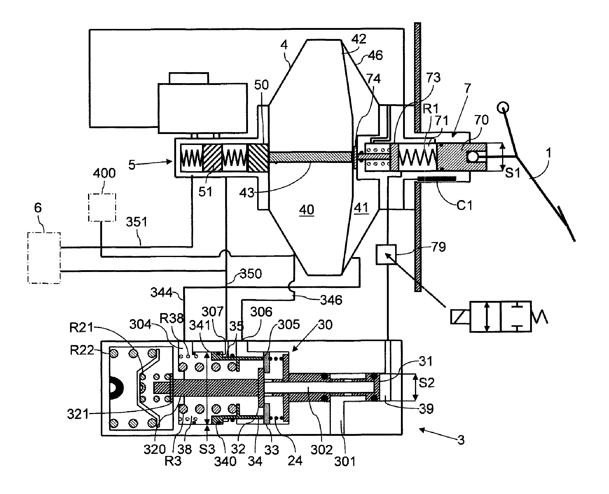
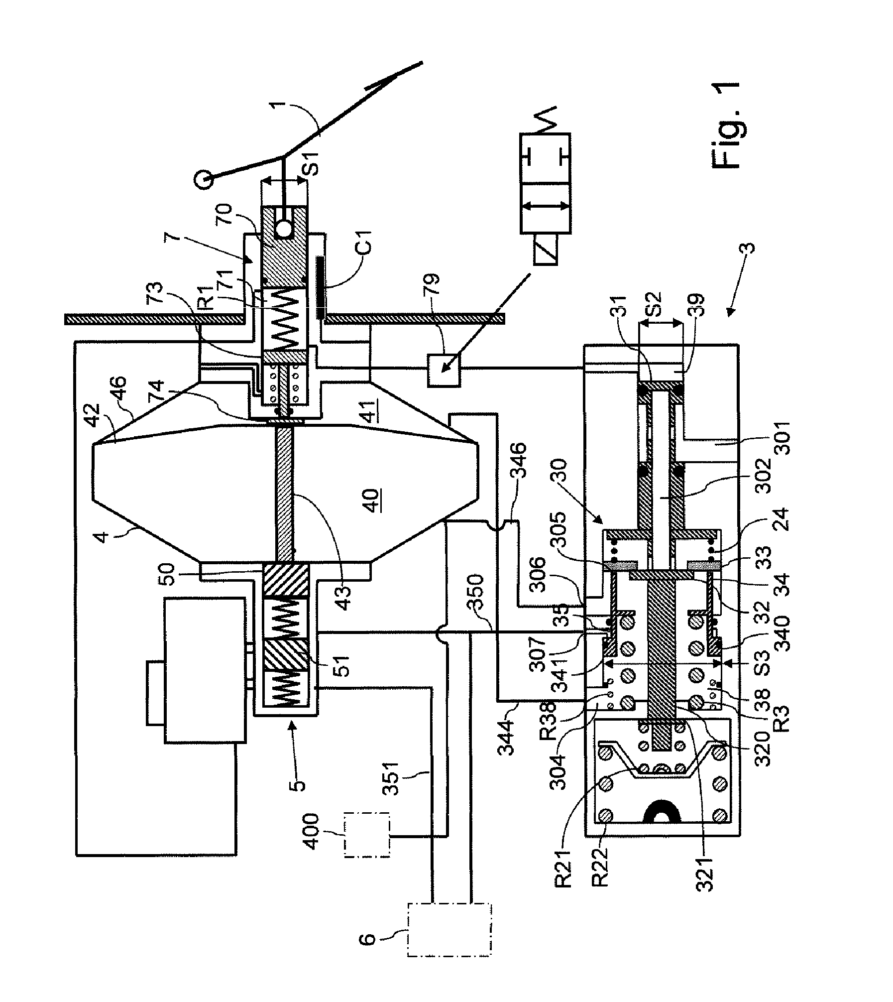
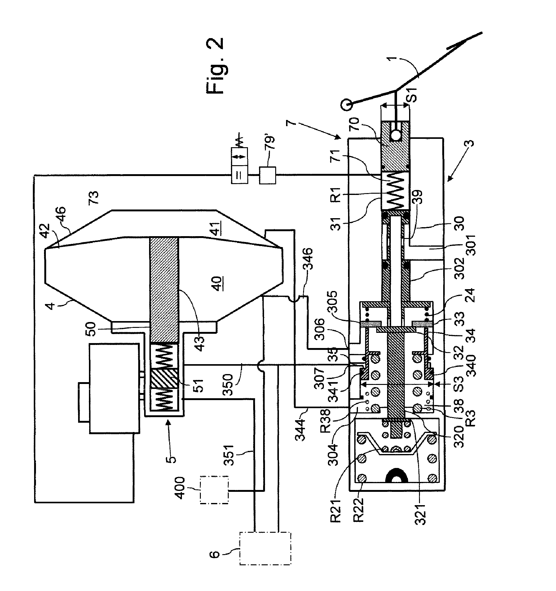
[0047]Referring to FIG. 1, an embodiment of the braking circuit control system according to the invention will now be described.

[0048]Said system comprises in the known manner a brake booster 4 which will be denoted “brake servo” in the description which follows and which comprises a working chamber 41 and a vacuum chamber 40 separated by a diaphragm or brake servo piston 42 able to be displaced along the axis of the brake servo 4. The displacement of the piston 42 controls, by means of a push rod 43, the displacement of the pistons 50, 51 of a brake master cylinder 5. Said master cylinder generates pressures in the braking circuits 6 of the vehicle.

[0049]According to the invention, an intermediate hydraulic or pneumatic device 3 is provided which will be denoted “simulator”3 in the remainder of the description.

[0050]A braking control device or brake pedal 1 which is actuated by the driver of the vehicle makes it possible to control a hydraulic actuating device 7 which is maintained...


PUM


Abstract

The invention relates to a braking control system for automotive vehicles comprising a braking control member (1), a brake booster (4) and a brake master cylinder (5). The system of the invention further comprises a simulator (3) coupled pneumatically to the piston (42) of the brake booster (4). Said simulator (3) receives at least one braking command from the braking control member (1) and makes it possible to establish, in return, a difference in pressure between the front chamber (40) and the rear chamber (41) of the brake booster so as to control the displacement of the piston (42).Application: Brakes for automotive vehicles.

Description

BACKGROUND OF THE INVENTION[0001]The invention relates to a braking control system for automotive vehicles and, in particular, a hydraulic control system. The invention also relates to mixed braking systems as provided in hybrid vehicles (vehicles having an electric drive and an internal combustion engine drive) comprising a hydraulically actuated braking system and an electric braking system using the electric traction motor(s) as electric generators.[0002]In the known prior art of hydraulic braking systems of automotive vehicles, a brake booster essentially has a housing comprising two chambers (the front chamber or vacuum chamber and the rear chamber or working chamber) separated by a mobile diaphragm fixed to a piston. A control rod may be displaced to the front of the vehicle when the driver of the vehicle actuates the brake pedal. This displacement of the control rod is transmitted to a plunger which actuates assistance means and the piston of the servomotor. Generally, said a...

Claims


Application Information

Patent Timeline
Patent Type & Authority Patents(United States)
IPC IPC(8): B60T8/44
CPCB60T8/4086B60T13/57
Inventor ANDERSON, CHRISSPROCQ, RAYNALDCHARPENTIER, CAROLE
Owner ROBERT BOSCH GMBH
Why Eureka
Try Eureka