

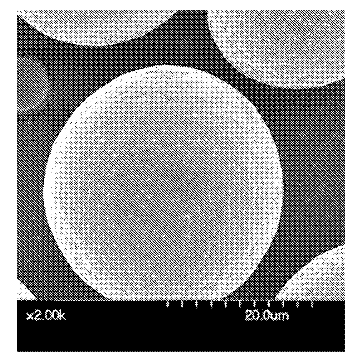
Production method of magnetic carrier and magnetic carrier produced therewith
a production method and magnetic carrier technology, applied in the field of magnetic carrier production method, can solve the problems of reducing the number of magnetic carriers, affecting the quality of magnetic carriers, so as to achieve the effect of reducing the number of resin composition particles
- Summary
- Abstract
- Description
- Claims
- Application Information
AI Technical Summary
Benefits of technology
Problems solved by technology
Method used
Image

Examples
example 1
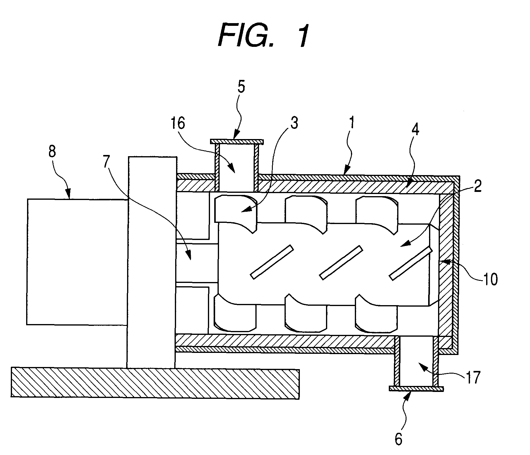
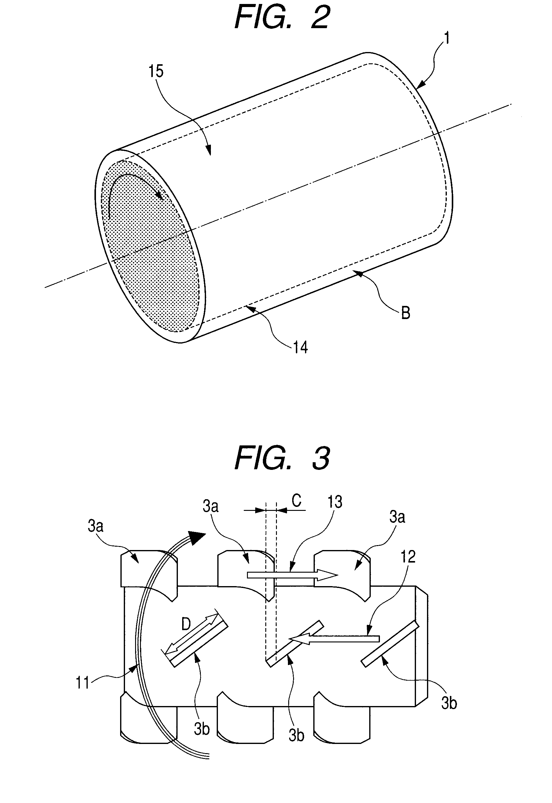
[0202]In the present Example, an apparatus provided with a cylindrical body casing 1 having an inner diameter of 130 mm and a driver 8 having a rating power of 5.5 kW was used for coating. Furthermore, materials and a production method shown below were used to produce a magnetic carrier.
[0203]In the present Example, a volume A of the magnetic carrier core a and resin composition particles, which are materials to be processed, was set to 5.7×10⁻⁴ m3 and a volume B thereof was set to 2.7×10⁻⁴ m3, and thereby A / B was set to 2.1.
[0204]Furthermore, the maximum width D of the stirring member 3 was set to 25.0 mm and a length of the rotor 18 constituting the rotor 2 was controlled, thereby an overlapping width C of the stirring member 3a and the stirring member 3b was set to 4.3 mm and C / D3a and C / D3b were set to 0.17.
[0205]With the above-mentioned apparatus configuration, to 100.0 parts by mass of the magnetic carrier core particles a, 1.5 parts by mass of the resin composition particles ...
examples 2 to 16
[0239]Magnetic carriers were prepared in a manner similar to Example 1 except that the conditions were changed to the conditions shown in Table 2. As the result that the power of a driver 8 was controlled so as to be constant at 3.5 kW, a peripheral speed of the stirring member became a value shown in Table 2.
[0240]The resulting magnetic carriers were subjected to evaluation similar to Example 1 and the results thereof are shown in Table 3.
example 17
[0241]In the apparatus used in Example 1, an overlapping width C of the stirring member 3a and the stirring member 3b was set to 4.3 mm and C / D3a and C / D3b were set to 0.17.
[0242]With the above-mentioned apparatus configuration, the coating was conducted by adding 0.5 parts by mass of resin composition particles 1 as a first input amount (input amount E) to 100.0 parts by mass of magnetic carrier core a. During the coating, a processing time was set to 10 minutes and a peripheral speed of the outermost end of the stirring member 3 was adjusted to 11 m / sec. The coating conditions are shown in Table 2.
[0243]After the processing time passed and the rotor 2 stopped rotating, in a state where the material to be processed was in the body casing 1, a raw material inlet 5 was opened, 1.5 parts by mass of the resin composition particles 1 were added as a second input amount (input amount F), followed by coating under the same operation conditions as the above.
[0244]The resulting magnetic car...
PUM
| Property | Measurement | Unit |
|---|---|---|
| particle diameter | aaaaa | aaaaa |
| particle diameter | aaaaa | aaaaa |
| particle diameter | aaaaa | aaaaa |
Abstract
Description
Claims
Application Information