
External hanging combined vacuum on-load tap switch

a combined vacuum and tap switch technology, applied in the field of external hanging combined vacuum on-load tap switch, can solve the problems of increasing the volume of the transformer, unforeseen losses and further problems, and long maintenance tim

Active Publication Date: 2012-12-11
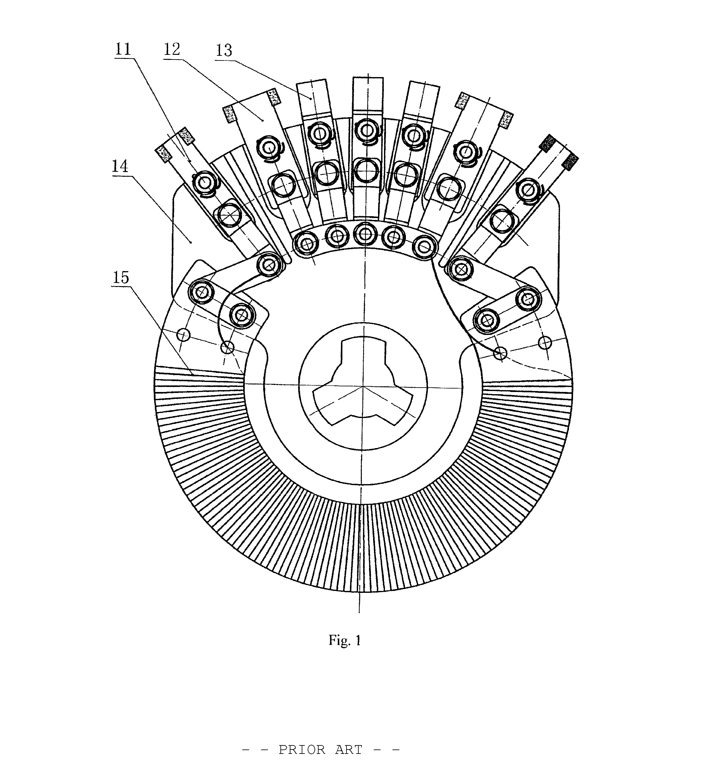
SHANGHAI HUAMING POWER EQUIP CO LTD
View PDF7 Cites 3 Cited by
  • Summary
  • Abstract
  • Description
  • Claims
  • Application Information

AI Technical Summary

Benefits of technology

The solution enables operation at high voltages and large currents with reduced transformer volume, simplified maintenance, and enhanced reliability by preventing oil contamination, as the switch is hung externally and uses vacuum pipe contactors to improve breaking capacity and prevent electric arc pollution.

Problems solved by technology

The above mentioned structure has following disadvantages:(1) A space needs to be reserved in the transformer for the switch, thereby increasing the volume of the transformer;(2) The failure maintenance and regular examination for the switch are relatively troublesome, as the transformer needs to be fully discharged with oil and covered with suspension, thus resulting in relatively a high maintenance cost and long maintenance time; and(3) The transformer may be polluted from potential leakage or damage in the oil chamber containing the switch, thereby causing unforeseen losses and further problems.
Limited by its structure, the combined on-load tap switch is useful only for relatively low voltages and small capacity on-load tapping, and not suitable for use in high voltages and large currents.
However, as the type M switch only has a Y-type connection mode, a large Δ connection transformer would need three type M switches, each of which respectively controls one phase of the transformer, thereby increasing the volume of the transformer, as well as wiring difficulty and cost.

Method used


Image

  • External hanging combined vacuum on-load tap switch
  • External hanging combined vacuum on-load tap switch
  • External hanging combined vacuum on-load tap switch

Examples


Embodiment Construction

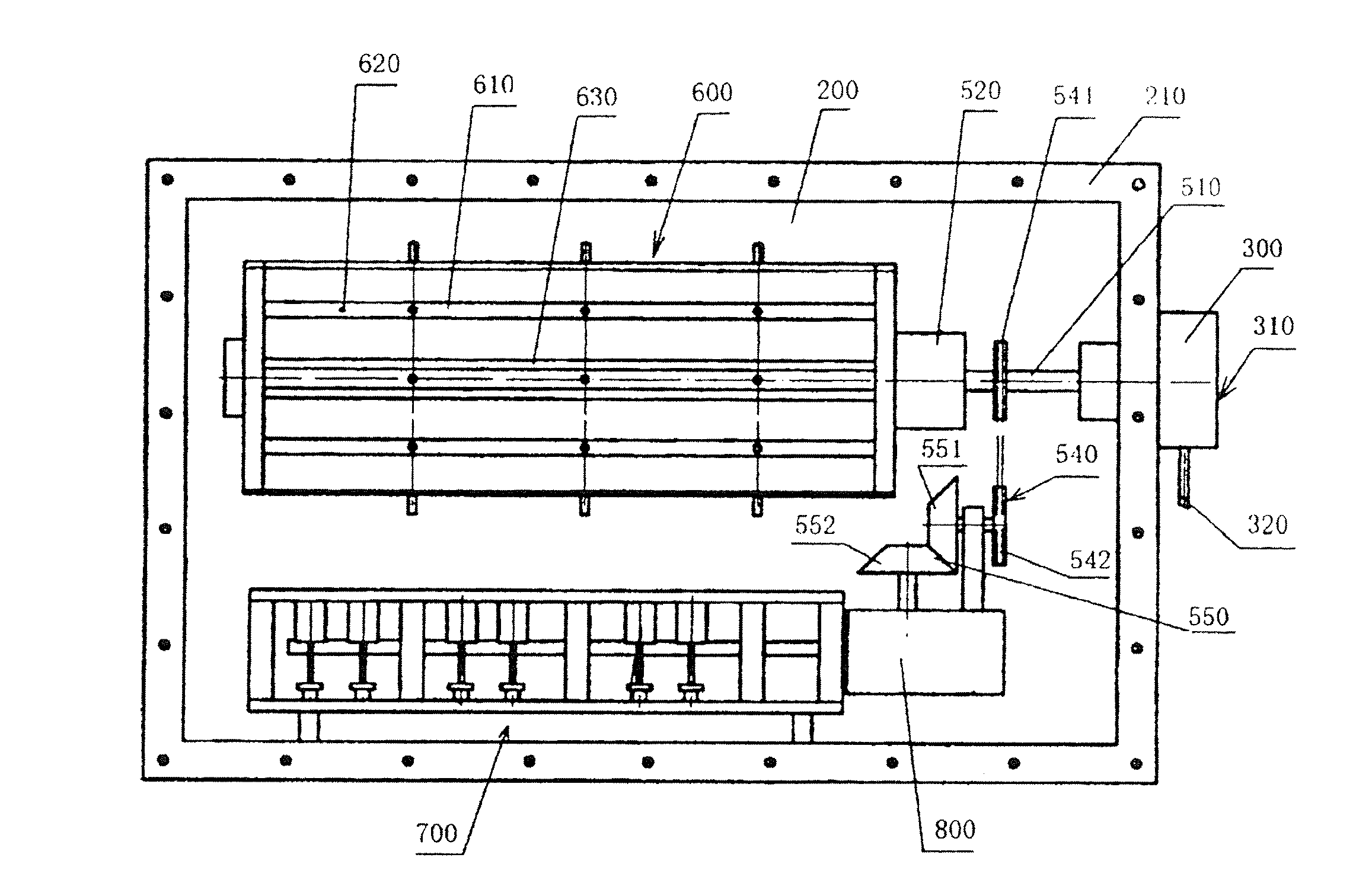
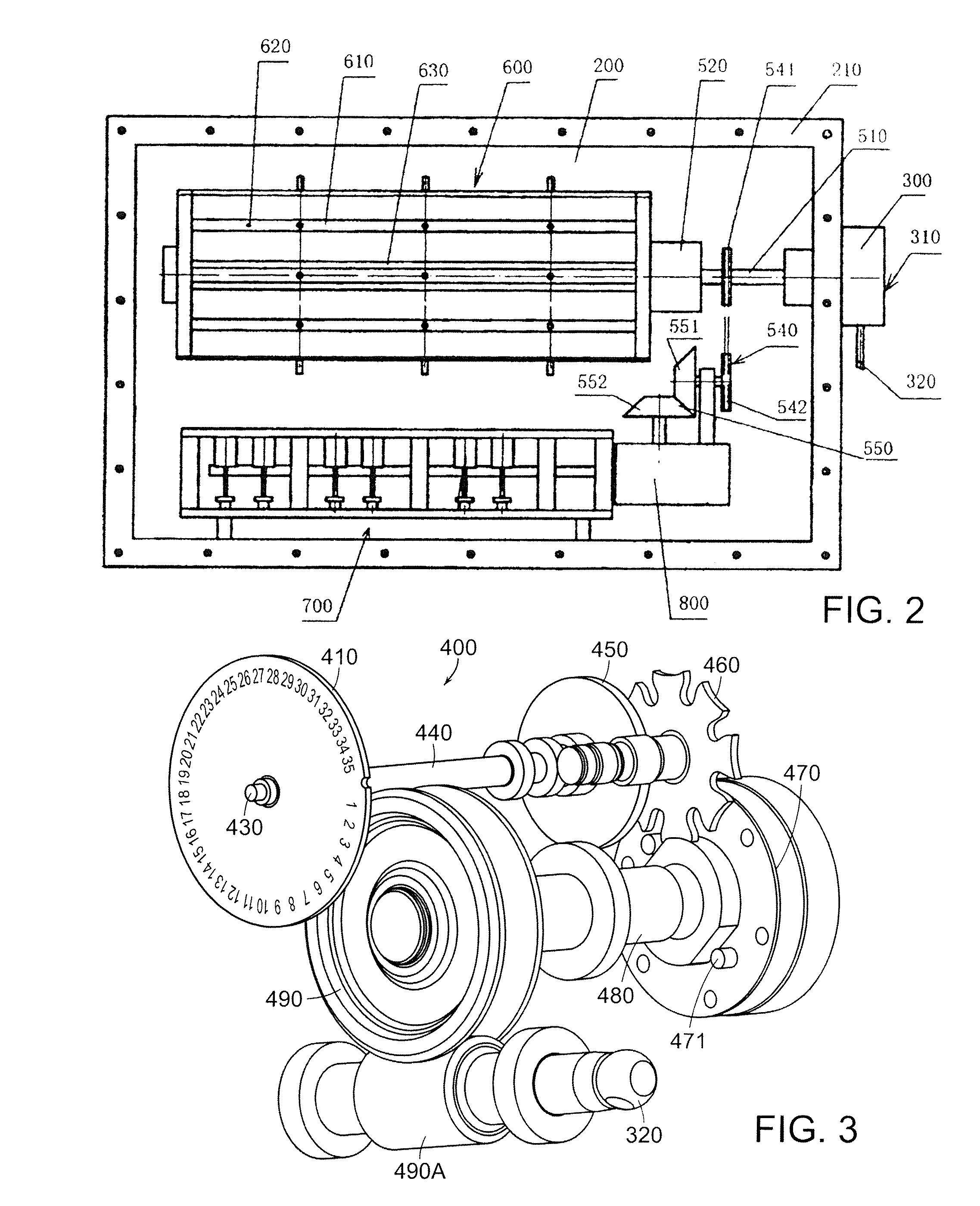
[0048]As shown in FIG. 2, the external hanging combined vacuum on-load tap switch comprises a case 200. A flange plate 210 is arranged at one side of the case 200. The flange plate 210 is used for butt-connecting with a flange (not shown) arranged on a transformer. The case is hung outside the oil tank of the transformer to form an external hanging tap switch.

[0049]A worm gear box 300 is arranged at the other side wall of the case 200, and the worm gear box 300 comprises a worm gear box body welded on one side of the case 200 and a transparent worm gear box cover 310 fixed on the worm gear box through a plurality of fastening bolts.

[0050]As shown in FIG. 3 and FIG. 4, a grade level clock indicating device 400 is arranged inside the worm gear box. The grade level clock indicating device 400 comprises a clock indicating plate 410, a clock finger, a clock finger rotating shaft 430, a rotating shaft sleeve 440, a driven plate 450, a Geneva wheel 460, a driving plate 470, a driving plate...


PUM


Abstract

The invention relates to an external hanging combined vacuum on-load tap switch, comprising a case, a tap selector, a switching means assembly, a transmission device, and one electric operation mechanism, wherein one lateral side wall of the case is provided with a connecting terminal connected with the coil tap of a transformer; the external side of the wall is provided with a first flange plate and is connected with a second flange plate of the transformer; the tap selector and the switching means assembly are arranged inside the case in parallel; and the electric operation mechanism is connected with the transmission device and drives the tap selector and the switching means assembly to achieve tapping and switching through the transmission device.

Description

CROSS REFERENCE TO RELATED APPLICATION[0001]This application claims the benefit of priority under 35 U.S.C. §119(a) to Chinese Patent Application No. 200810033900.0, filed Feb. 26, 2008, which is hereby incorporated by reference in its entirety.FIELD OF THE INVENTION[0002]The invention relates to an on-load tap switch, and more specifically, to an external hanging combined vacuum on-load tap switch used to accompany a transformer.BACKGROUND[0003]The on-load tap switch changes the primary and secondary ratio of transformer windings by switching the multi-tap transformer from one tap to another when the transformer is loaded, thereby changing the output voltage of the transformer.[0004]In the prior art, the combined on-load tap switch usually includes a switching means and a tap selector. Generally speaking, the switching means is arranged at the top, while the tap selector is arranged at the bottom, and the switching means and the tap selector are arranged co-axially and mechanically...

Claims


Application Information

Patent Timeline
Patent Type & Authority Patents(United States)
IPC IPC(8): H01H25/00
CPCH01H9/0038H01F29/04H01H9/0033
Inventor XIAO, RIMING
Owner SHANGHAI HUAMING POWER EQUIP CO LTD
Learn More