Surface acoustic wave resonator, surface acoustic wave oscillator, and surface acoustic wave module unit

a technology of surface acoustic wave and surface acoustic wave, which is applied in the direction of oscillator, piezoelectric/electrostrictive device details, piezoelectric/electrostrictive/magnetostrictive devices, etc., can solve the problem that the characteristics of the surface acoustic wave resonator cannot be satisfactorily obtained, and achieves the effect of reducing size, reducing q value and small siz

Active Publication Date: 2013-01-01
SEIKO EPSON CORP
View PDF15 Cites 66 Cited by
  • Summary
  • Abstract
  • Description
  • Claims
  • Application Information

AI Technical Summary

Benefits of technology

[0010]Regarding the standing waves of the surface acoustic waves generated in the surface acoustic wave resonator, the vibration displacement is large at the center of the IDT and is small at both edges thereof. The line occupying ratio causing the increase in electromechanical coupling coefficient is selected for the center having the large vibration displacement so as to suppress an increase in CI value, and the line occupying ratio causing the increase in reflection of the surface acoustic waves is selected for the edges having the small vibration displacement so as to enhance the confinement of vibration energy in the IDT. Accordingly, it is possible to implement a surface acoustic wave resonator with excellent CI value and Q value.
[0034]According to this configuration, since the surface acoustic wave resonator having the enhanced Q value and the reduced size is mounted, it is possible to provide a surface acoustic wave module unit having a small size.

Problems solved by technology

With the decrease in the size of the surface acoustic wave resonator, there is a problem in that a decrease in Q value or an increase in CI value is caused and thus the characteristics of the surface acoustic wave resonator cannot be satisfactorily obtained.

Method used


Image

  • Surface acoustic wave resonator, surface acoustic wave oscillator, and surface acoustic wave module unit
  • Surface acoustic wave resonator, surface acoustic wave oscillator, and surface acoustic wave module unit
  • Surface acoustic wave resonator, surface acoustic wave oscillator, and surface acoustic wave module unit

Examples


first embodiment

(First Embodiment)

[0070]A surface acoustic wave resonator according to a first embodiment of the invention will be described below.

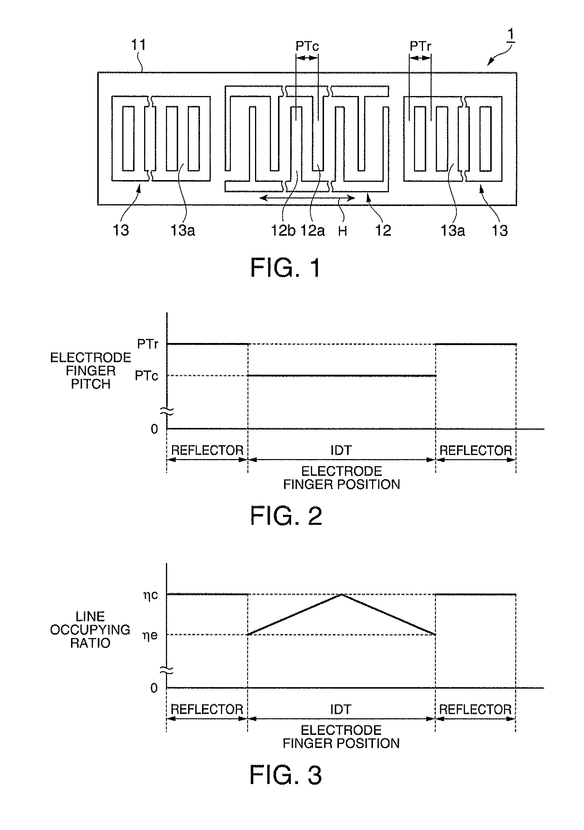
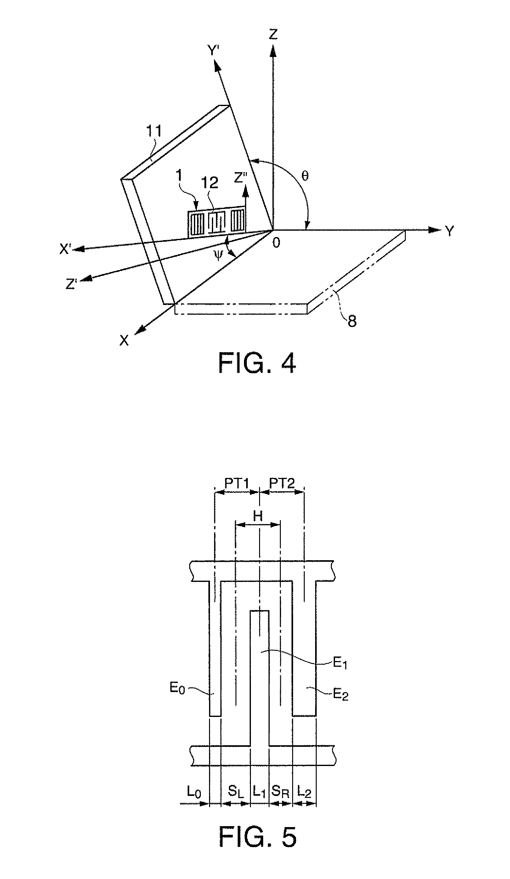
[0071]FIG. 1 is a plan view schematically illustrating the configuration of a surface acoustic wave resonator according to this embodiment. FIG. 2 is a diagram illustrating the relation between an electrode finger position and an electrode finger pitch in the surface acoustic wave resonator according to this embodiment. FIG. 3 is a diagram illustrating the relation between the electrode finger position and a line occupying ratio in the surface acoustic wave resonator according to this embodiment. FIG. 4 is a diagram illustrating a cutout angle of a crystal substrate and a traveling direction of surface acoustic waves. FIG. 5 is a diagram schematically illustrating the line occupying ratio.

[0072]As shown in FIG. 1, the surface acoustic wave resonator 1 includes an IDT 12 having a comb-like electrode and a pair of reflectors 13 disposed with the IDT 12 int...

second embodiment

(Second Embodiment)

[0123]A surface acoustic wave resonator according to a second embodiment of the invention will be described below. Although the IDT is weighted using the line occupying ratio, but the IDT is weighted using both the line occupying ratio and the electrode finger pitch in this embodiment.

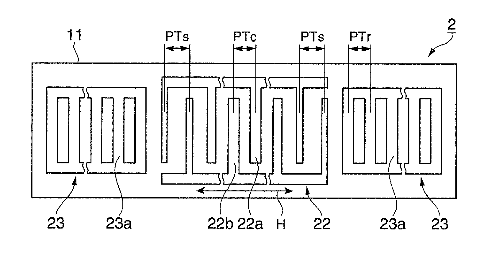
[0124]FIG. 10 is a plan view schematically illustrating the configuration of a surface acoustic wave resonator according to this embodiment. FIG. 11 is a diagram illustrating the relation between the electrode finger position and the electrode finger pitch in the surface acoustic wave resonator according to this embodiment. FIG. 12 is a diagram illustrating the relation between the electrode finger position and the line occupying ratio in the surface acoustic wave resonator according to this embodiment.

[0125]As shown in FIG. 10, a surface acoustic wave resonator 2 includes an IDT 22 having a comb-like electrode and a pair of reflectors 23 disposed with the IDT 22 interposed therebetw...

third embodiment

(Third Embodiment)

[0150]A surface acoustic wave resonator according to a third embodiment of the invention will be described below. In this embodiment, the IDT is weighted using the line occupying ratio and the electrode finger pitch and a region having a constant electrode finger pitch is disposed at the center of the IDT.

[0151]FIG. 15 is a plan view schematically illustrating the configuration of a surface acoustic wave resonator according to this embodiment. FIG. 16 is a diagram illustrating the relation between the electrode finger position and the electrode finger pitch in the surface acoustic wave resonator according to this embodiment. FIG. 17 is a diagram illustrating the relation between the electrode finger position and the line occupying ratio in the surface acoustic wave resonator according to this embodiment.

[0152]As shown in FIG. 15, a surface acoustic wave resonator 3 includes an IDT 32 having a comb-like electrode and a pair of reflectors 33 disposed with the IDT 32 ...


PUM


Abstract

In a surface acoustic wave resonator in which an IDT having electrode fingers for exciting surface acoustic waves is formed on a crystal substrate, the line occupying ratio causing the maximum electromechanical coupling coefficient and the line occupying ratio causing the maximum reflection of the surface acoustic waves in the IDT are different from each other, the center of the IDT has the line occupying ratio causing an increase in electromechanical coupling coefficient in comparison with the edges of the IDT, and the edges of the IDT have the line occupying ratio causing an increase in reflection of the surface acoustic waves in comparison with the center of the IDT.

Description

TECHNICAL FIELD[0001]The present invention relates to a surface acoustic wave resonator employing a piezoelectric substrate, a surface acoustic wave oscillator, and a surface acoustic wave module unit.BACKGROUND ART[0002]Conventionally, surface acoustic wave resonators using surface acoustic waves (SAW) have been widely used in electronic apparatuses.[0003]With the recent spread of portable devices, a decrease in the size of a surface acoustic wave resonator used therein has been required. With the decrease in the size of the surface acoustic wave resonator, there is a problem in that a decrease in Q value or an increase in CI value is caused and thus the characteristics of the surface acoustic wave resonator cannot be satisfactorily obtained.[0004]As a countermeasure, for example, PTL 1 discloses a technique of enhancing the Q value by reducing a line width ratio (a line occupying ratio) which is a ratio of an electrode finger width to an electrode finger pitch in a comb-like elect...

Claims


Application Information

Patent Timeline
Patent Type & Authority Patents(United States)
IPC IPC(8): H01L41/04H03H9/64H03B5/30
CPCH03H9/02551H03H9/0547H03H9/14517H03H9/643H03H9/1457H03H9/14582H03H9/25H03H9/14555H03H9/145H03B5/30
Inventor YAMANAKA, KUNIHITO
Owner SEIKO EPSON CORP
Why Eureka
Try Eureka