Microphone devices and methods for tuning microphone devices

a microphone and microphone technology, applied in the direction of electrical transducers, piezoelectric/electrostrictive transducers, transducer types, etc., can solve the problems of significant variation in mass and stiffness, difficult to manufacture diaphragms with well-defined responses, and differences between the responses of diaphragms and the microphone elements and devices in which they are used, so as to reduce the concentration of metal

Active Publication Date: 2013-01-01
THE ARIZONA BOARD OF REGENTS ON BEHALF OF THE UNIV OF ARIZONA
View PDF15 Cites 29 Cited by
  • Summary
  • Abstract
  • Description
  • Claims
  • Application Information

AI Technical Summary

Problems solved by technology

However, manufacturing diaphragms with well-defined responses is relatively difficult.
In particular, nanoscale statistical irregularities caused by the nature of the materials of the diaphragms and manufacturing variations in deposition, lithography, and etch methods lead to significant variation in mass and stiffness.
The variations in mass and stiffness, in turn, lead to differences of the responses of the diaphragms and of the microphone elements and devices in which they are used.
Moreover, environmental factors such as oxidation, condensation of airborne vapors and contamination can alter the diaphragm after the structure has been fabricated.
However, fabrication of closely matched microphone elements can be difficult due to manufacturing variations.
Even a small difference in response, e.g., as little as 0.2 dB, can destroy directionality completely.
Electronic calibration and compensation can also be used to achieve directionality, but such methods are very complex, require large systems and large power consumption, and lead to high costs.
Manually selecting matched microphone elements can provide limited success, but matching involves high cost and requires additional matching after installation of the device.
Hearing aids are, however, not a one-size-fits-all solution to hearing problems.
A patient's level or type of hearing impairment and / or physical condition can impact sound delivery within the ear, making a universal fit impossible.
There currently exist no low-cost, effective methods for in situ tuning.

Method used


Image

  • Microphone devices and methods for tuning microphone devices
  • Microphone devices and methods for tuning microphone devices
  • Microphone devices and methods for tuning microphone devices

Examples


examples

[0055]The invention can be further described by the following non-limiting Examples.

[0056]A microphone element according to the present invention was fabricated according to a procedure analogous to that described above with referenced to FIG. 6. In this microphone element, the suspended diaphragm has two layers of parylene films, a thin parylene layer underneath the top electrode, and a thicker parylene layer on top of the electrode. C-type parylene is used for the diaphragm material because of its excellent electrical / mechanical properties. The first parylene layer (3000-Å thick) is coated on a 1-μm thick sacrificial oxide layer on a silicon wafer to provide electrical isolation between the top and bottom electrodes. The parylene diaphragm is patterned by etching in an oxygen plasma for 1.5 min at an etch rate of 2000 Å / min under 15 sccm oxygen, 100 W RF power, and 500 V bias. A 3000 Å thick top electrode (Cr / Au) is then deposited and patterned on this first parylene layer. The se...


PUM


Abstract

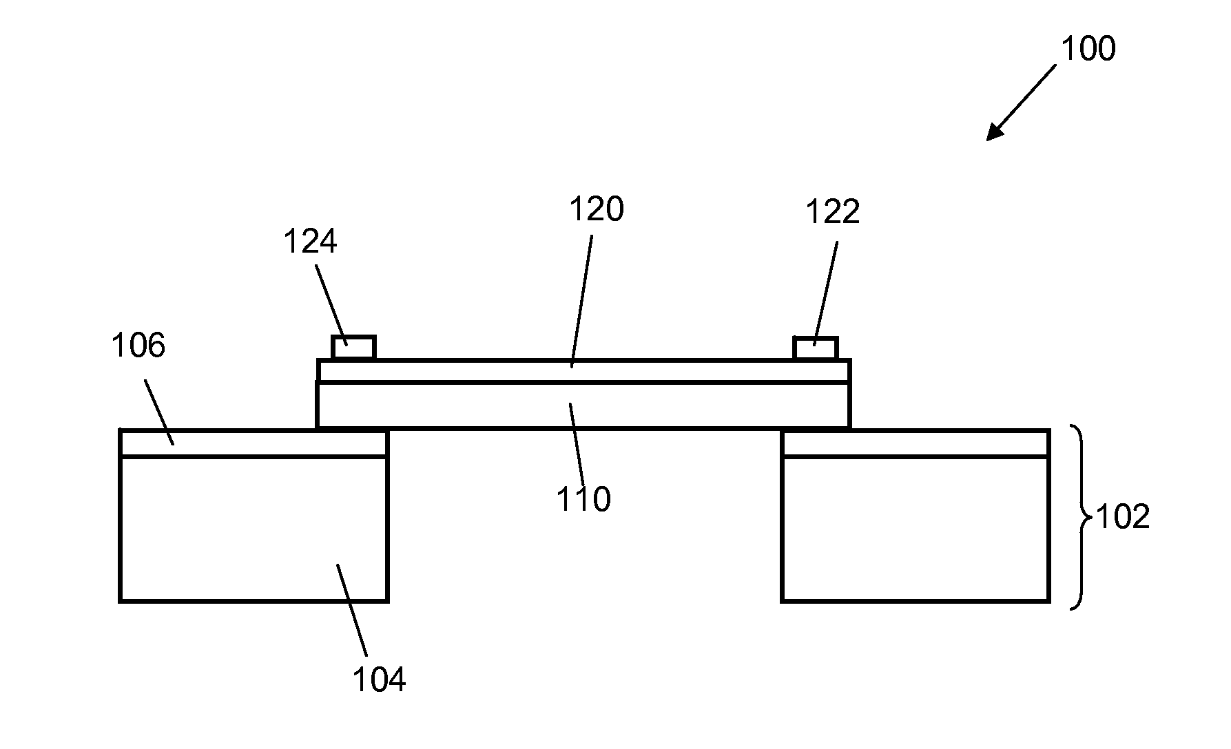
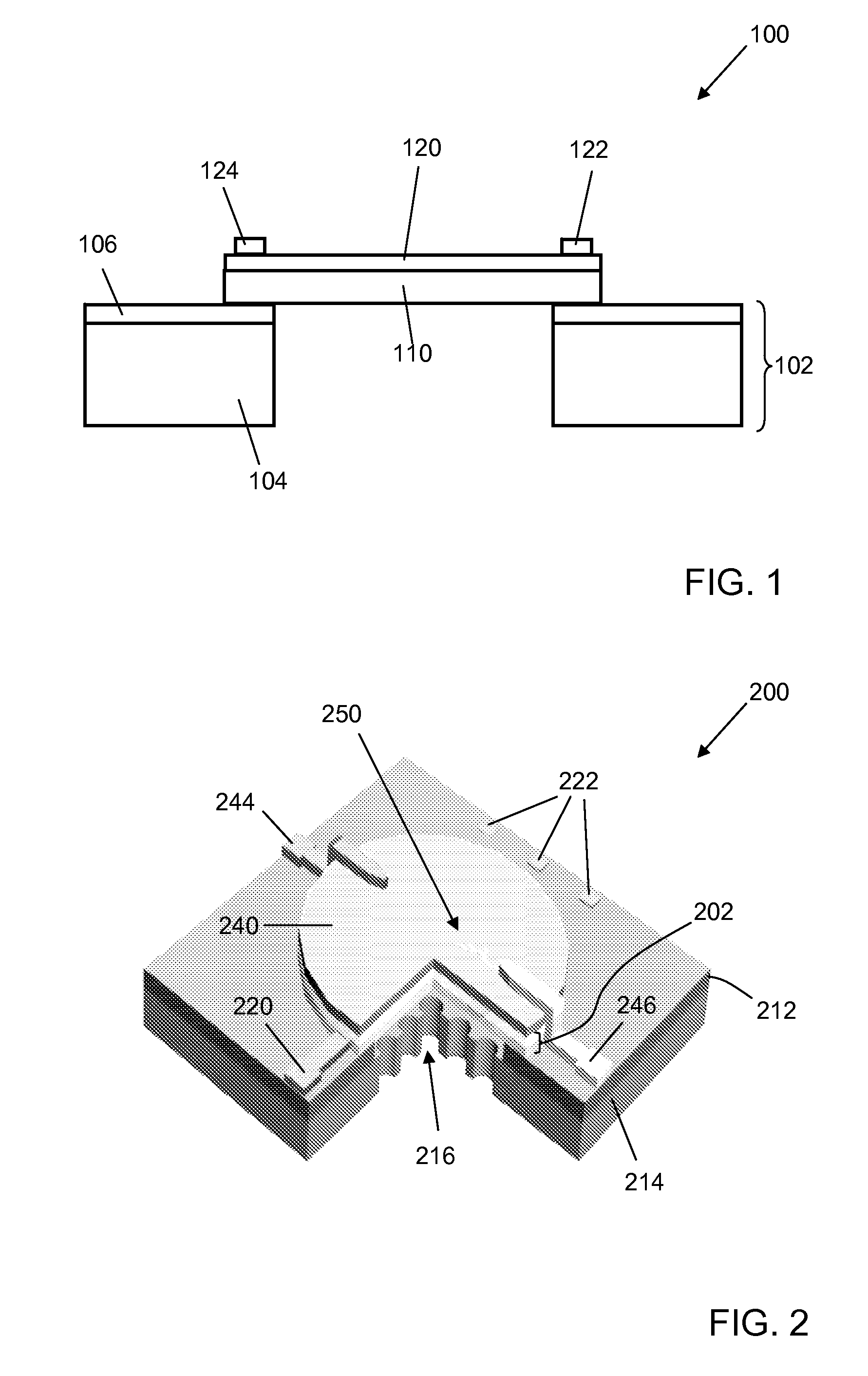
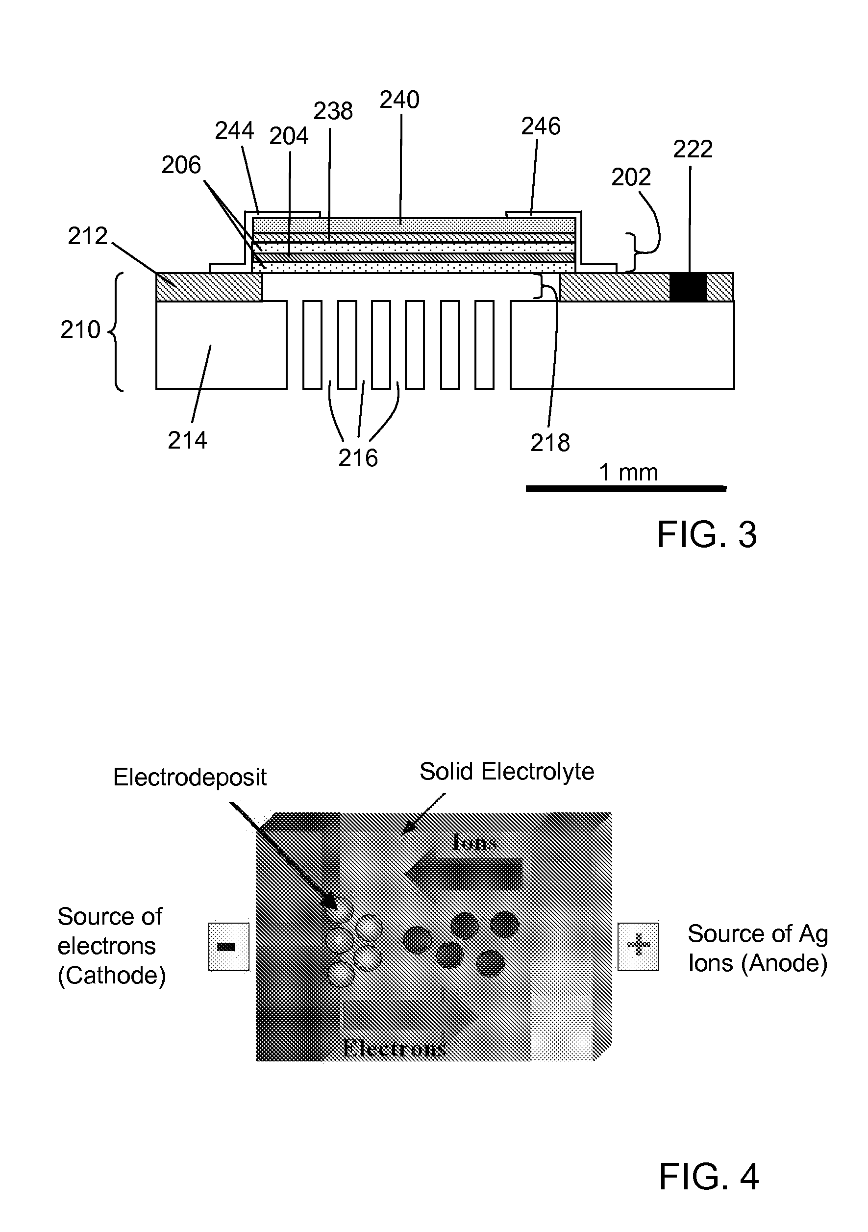
The present invention relates generally to microphone devices useful, for example, in hearing aid devices. The present invention relates more particularly to tunable microphone devices, and methods used to tune them. One aspect of the present invention is a microphone device that includes at least one microphone element. Each microphone element comprises a diaphragm suspended by a substrate; a solid electrolyte disposed on the diaphragm; an anode electrically coupled to the solid electrolyte; and a cathode electrically coupled to the solid electrolyte. The solid electrolyte is disposed between the anode and the cathode, such that ions flowing from the anode to the cathode travel through the solid electrolyte and electrons can flow in the opposite direction.

Description

CROSS-REFERENCE TO RELATED APPLICATIONS[0001]This application claims priority to U.S. Provisional Patent Application Ser. No. 60 / 988,800, filed Nov. 18, 2007, which is hereby incorporated herein by reference in its entirety.BACKGROUND OF THE INVENTION[0002]1. Field of the Invention[0003]The present invention relates generally to microphone devices useful, for example, in hearing aid devices. The present invention relates more particularly to tunable microphone devices, and methods used to tune them.[0004]2. Technical Background[0005]Microphone devices generally include a diaphragm that is somewhat flexible and moveable by acoustic force. However, manufacturing diaphragms with well-defined responses is relatively difficult. In particular, nanoscale statistical irregularities caused by the nature of the materials of the diaphragms and manufacturing variations in deposition, lithography, and etch methods lead to significant variation in mass and stiffness. The variations in mass and st...

Claims


Application Information

Patent Timeline
Patent Type & Authority Patents(United States)
IPC IPC(8): H04R9/08
CPCH04R19/04
Inventor CHAE, JUNSEOKKOZICKI, MICHAEL
Owner THE ARIZONA BOARD OF REGENTS ON BEHALF OF THE UNIV OF ARIZONA
Why Eureka
Try Eureka