Method and system for error correction in transmitting data using low complexity systematic encoder

a systematic encoder and low-complexity technology, applied in the field of error correction, can solve the problems of unacceptably high encoder complexity, inability to transform a non-systematic polar code into a systematic polar code, and low practical use of high-complexity encoder schemes. achieve the effect of improving the bit-error rate performan

Active Publication Date: 2013-01-01
POLARAN YAZILIM BILISIM DANISMANLIK ITHALAT IHRACAT SANAYI TICARET SIRKETI
View PDF7 Cites 109 Cited by
  • Summary
  • Abstract
  • Description
  • Claims
  • Application Information

AI Technical Summary

Benefits of technology

[0008]This disclosure describes a systematic variant of polar coding complete with an encoder and decoder that preserves the low-complexity properties of standard non-systematic polar coding while significantly improving its bit-error rate (BER) performance.
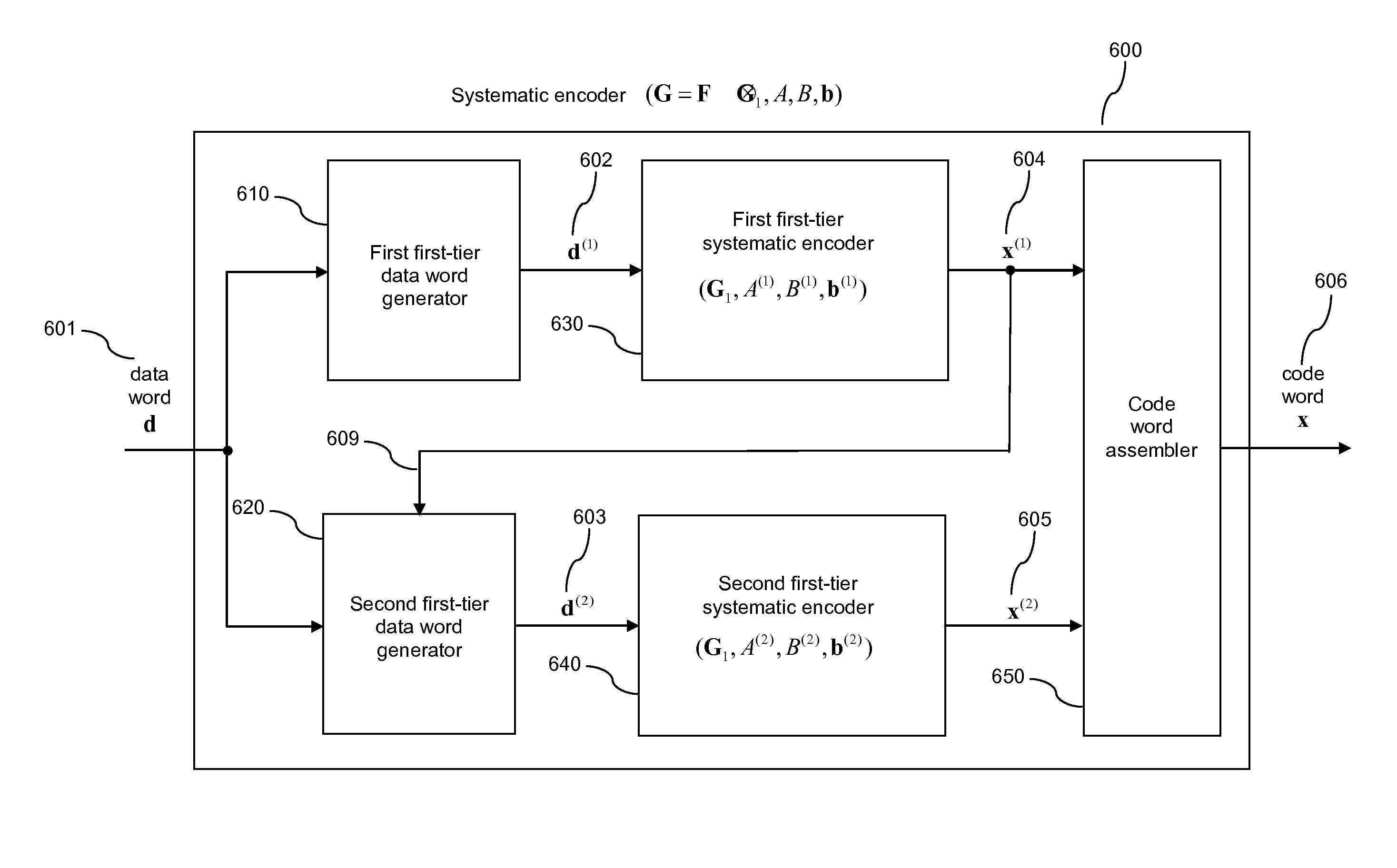
[0010]Accordingly, an encoding assembly is implemented by an electrical circuit or by a processor accessing a computer readable storage medium storing instructions executable by the processor to implement a coding circuit to establish a systematic encoder for a code C to encode data prior to transmission of the data to ameliorate the effects of noise. The code C is an affine subspace of a range space of a transform G, and the transform G has a form P(F1G1)Q, wherein P is a row-permuter, F1 is a first kernel transform, G1 is a first-tier transform, and Q is a column permuter. The row permuter is a permutation matrix and likewise the column permuter is a permutation matrix. According to this aspect, the first kernel transform F1 has a size greater than one, while the first-tier transform has a size smaller than a size of the transform G. The coding circuit being configured to derive from an input data word d a plurality of first-tier data words d(1), . . . , d(k) to be encoded into a plurality of respective first-tier code words x(1), . . . , x(k). The plurality of code words belong to a plurality of respective first-tier codes C1, . . . , Ck, with the plurality of first-tier codes being equal to respective first-tier affine subspaces of the first-tier transform G1. For each i from 1 to k, the circuit carries out systematic encoding of the ith first-tier data word d(1) into an ith first-tier code word x(i). The ith first-tier code word x(i) belongs to the ith first-tier code Ci. Furthermore, the coding circuit combines the plurality of first-tier code words x(1), . . . , x(k) to obtain the code word x. In this way, systematic encoding for the code C is accomplished at low-complexity due to effective reduction of a given systematic encoding problem instance for the code C into a plurality of systematic encoding problem instances for the plurality of first-tier codes C1, . . . , Ck, with each code in the plurality of first-tier codes being smaller than the code C.
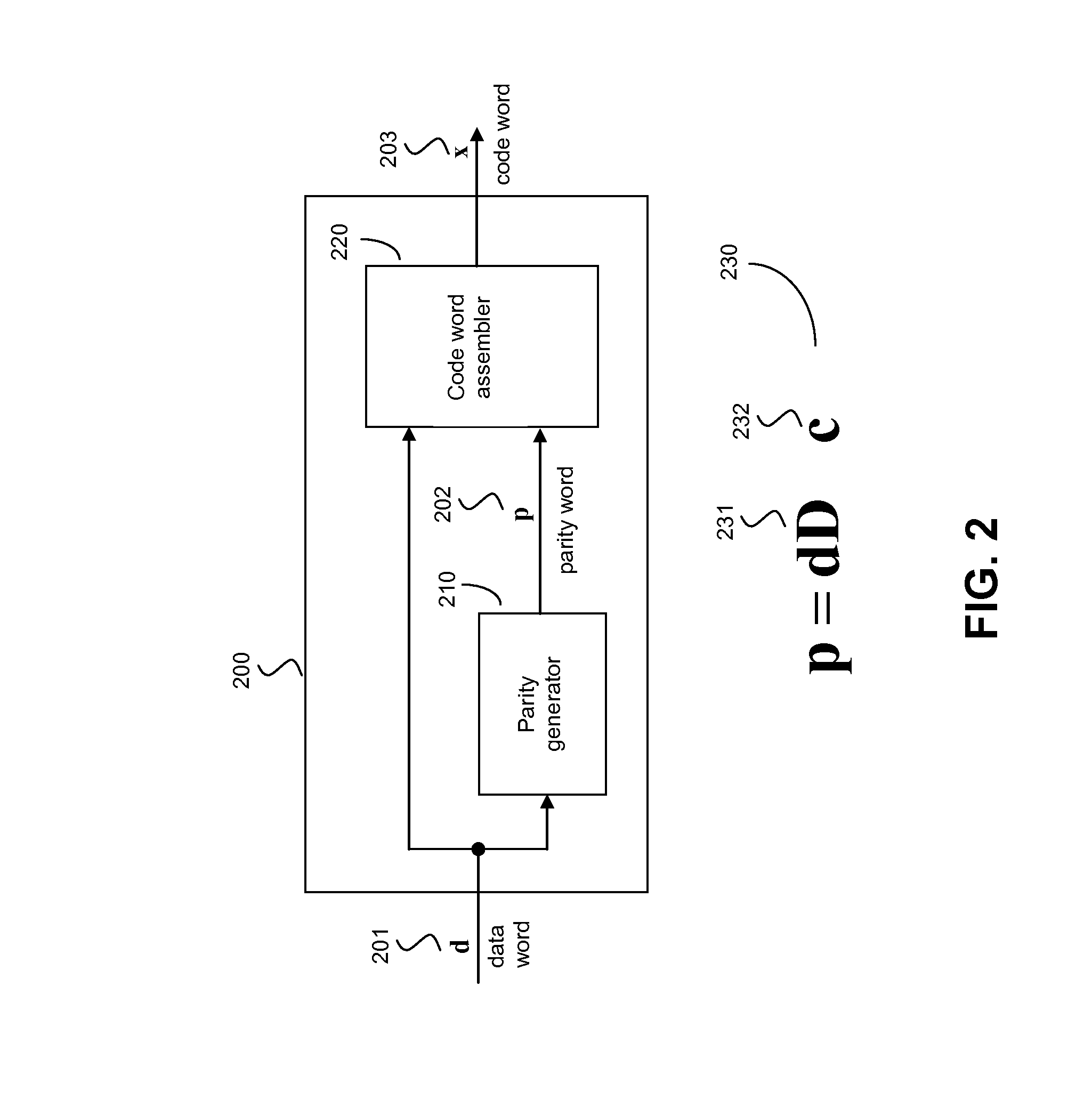
[0016]In another aspect, a systematic encoder assembly includes a parallelized hardware implementation of a systematic encoder. In this aspect, the parallelized hardware implementation includes a circuit configured for a transform G. This circuit contains memory and is configured for implementing local constraints. According to this aspect, the circuit propagates knowledge between parts of the memory by way of the local constraints. The circuit is initialized by a loading a data word into the memory, and the knowledge in the circuit initially includes a knowledge of the data word and a knowledge of a fixed word. The local constraints are used to gain new knowledge from existing knowledge iteratively according to a schedule of calculations, so that the memory can be updated in accordance with the new knowledge to derive a parity word such that a combination of the parity word and the data word is output as a code word for transmission thereof as a robust transform of the data word.

Problems solved by technology

Higher complexity encoding schemes that reduce the BER of a received signal but require too much computation for expected data transmission rates are of little practical use.
As recognized herein, however, conventional techniques cannot be used to transform a non-systematic polar code into a systematic polar code because doing so destroys the requisite recursive structure of the Kronecker power-based transform matrix G typically used in polar codes, which in turn implicates an unacceptably high encoder complexity.

Method used


Image

  • Method and system for error correction in transmitting data using low complexity systematic encoder
  • Method and system for error correction in transmitting data using low complexity systematic encoder
  • Method and system for error correction in transmitting data using low complexity systematic encoder

Examples


Embodiment Construction

[0027]In accordance with established conventions in coding theory, data words, parity words, and code words in the system are represented herein as vectors over a finite field Fq where q denotes the number of elements in the field. Field elements (scalars) are denoted by plain tower case letters, such as a∈Fq. Vectors over a field are denoted by lower-case boldface letters, such as a∈FqN where N denotes the length of the vector. The notation ai denotes the ith coordinate of a vector a. A vector a∈FqN is alternatively denoted in terms of its elements as (a1, . . . , aN) or (ai:1≦i≦N). Matrices over a field are denoted by upper-case boldface letters, such as A∈F qM×N where M denotes the number of rows and N denotes the number of columns of A. The notation ai,j denotes the element in the ith row and jth column of A. A matrix A∈FqM×N is denoted in terms of its elements as (ai,j:1≦i≦M,1≦j≦N). The size of a matrix A is defined as the number of elements in A; thus, the size of a matrix wit...


PUM


Abstract

A systematic encoder such as a systematic polar encoder for channel encoding to ameliorate the effects of noise in a transmission channel. The codeword carries a data word to be transmitted transparently, and also carries a parity part derived from the data word and a fixed word. Implementations advantageously reduce coding complexity to the order of N log(N), wherein N is the dimension of a matrix of the nth Kronecker power associated with a matrix effectively employed by the encoder.

Description

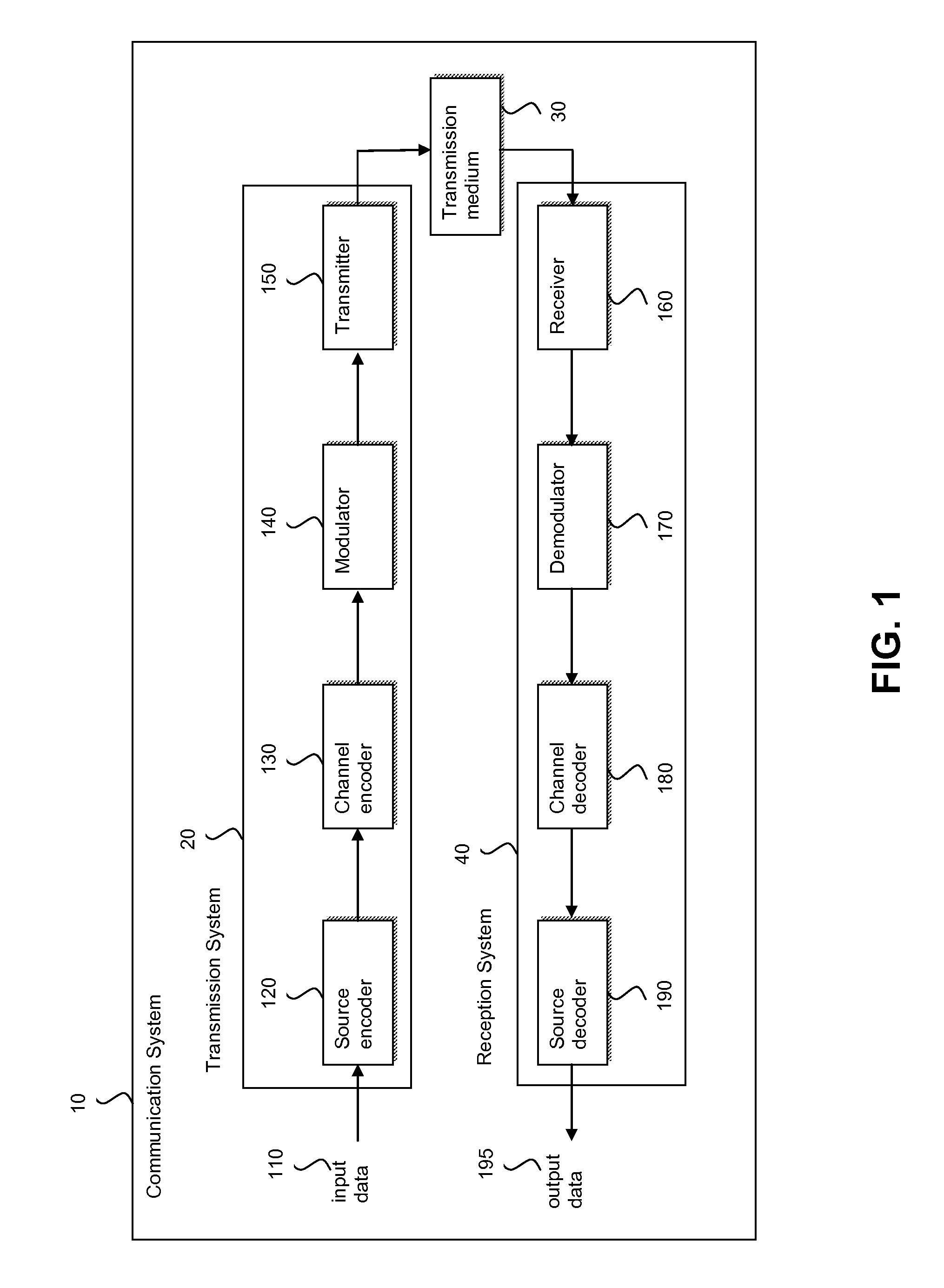
FIELD OF THE INVENTION[0001]The present application relates generally to error correction, and more particularly to providing a low complexity systematic encoder for error correction using polar codes.BACKGROUND[0002]In modern digital data transmission (wireless telephony, wireless data transmission, optical disk transmission to a player, music players receiving music data, and so on), a source encoder can compress the data to be transmitted for efficiency and then a channel encoder can receive the compressed data and add redundancy to it to protect the data against noise in the transmission channel. The receiver (sometimes referred to as the “sink”) at the other end of the channel receives the encoded data and uses a channel decoder to perform the inverse of channel encoding, followed by a source decoder which performs the inverse of source encoding. The decoded information is then played by the sink, e.g., by an optical disk player or music player or receiving telephone as audio, ...

Claims


Application Information

Patent Timeline
Patent Type & Authority Patents(United States)
IPC IPC(8): H03M13/00
CPCH03M13/611H03M13/13H04L1/0009H04L1/0057H03M13/1148H03M13/615H04L1/0041H04L1/0043H04L12/4633
Inventor ARIKAN, ERDAL
Owner POLARAN YAZILIM BILISIM DANISMANLIK ITHALAT IHRACAT SANAYI TICARET SIRKETI
Why Eureka
Try Eureka