Apparatus and methods for measuring defibrillation lead impedance via a high magnitude, short duration current pulse

a technology of defibrillation lead and high magnitude, applied in the field of implantable medical devices, can solve the problems of inconsistent impedance measurement, inconsistent impedance measurement, and incomplete embodiment of icd devices, and achieve the effect of more accurate impedance measurements

Active Publication Date: 2013-01-08
KROLL MARK
View PDF12 Cites 32 Cited by
  • Summary
  • Abstract
  • Description
  • Claims
  • Application Information

AI Technical Summary

Benefits of technology

[0012]The present invention is directed to apparatus and methods for accurately measuring the impedance between defibrillation electrodes of an ICD device. In one embodiment, high current test pulse of a very short duration are delivered to determine the impedance between defibrillation electrodes. These short duration and high current test pulses are delivered at a voltage of at least about 75V but below the normal range of defibrillation shocks of 250-800V. Unlike current low voltage test pulse techniques, the high current test pulses produce more accurate impedance measurements. Because the pulses are shorter than the time periods required to sense pain by the human pain sensors, the high current test pulses are not perceived and therefore not painful to the patient.
[0016]In one embodiment, a capacitor arrangement separate from the main high voltage defibrillation capacitors is used in connection with the high voltage inverter / transformer and the high voltage switching circuit to isolate the main high voltage defibrillation capacitors from the defibrillation electrodes during the impedance testing. Unlike the prior art techniques, this embodiments permits a practical and efficient use of the ICD battery to power the test pulses while accomplishing more accurate impedance measurements. It also serves to insulate the patient from an unintentional shock of normal defibrillation magnitude as the result of a device failure by ensuring that the main defibrillation capacitors are only charged when treatment is necessary and are not required to be charged during impedance testing.

Problems solved by technology

Unfortunately, the fudge factor is not consistent with all types of leads, electrodes, patients, or changing electrolyte concentrations.
Thus, significant errors are often introduced that may yield inconsistent impedance measurements.
While this approach would somewhat improve the accuracy of the impedance measurement, unfortunately this embodiment is completed impractical for an ICD device as the continuous power requirement to implement this kind of square wave test pulse would be 50 W, an amount which is well above any continuous power supply that can be provided by current defibrillation battery technology of an ICD device.
While this approach has the added advantage of exercising the high voltage switches and can address some of the errors induced by the use of low voltage test shocks, the approach introduces the possibility of unwanted shocks in the event of a failure of the high voltage switches or heightened sensitivity of the patient to larger voltage shocks.
Defibrillation strength shocks (approximately ten amperes and several hundred volts) are extremely painful and cannot be given to conscious patients.

Method used


Image

  • Apparatus and methods for measuring defibrillation lead impedance via a high magnitude, short duration current pulse
  • Apparatus and methods for measuring defibrillation lead impedance via a high magnitude, short duration current pulse
  • Apparatus and methods for measuring defibrillation lead impedance via a high magnitude, short duration current pulse

Examples


Embodiment Construction

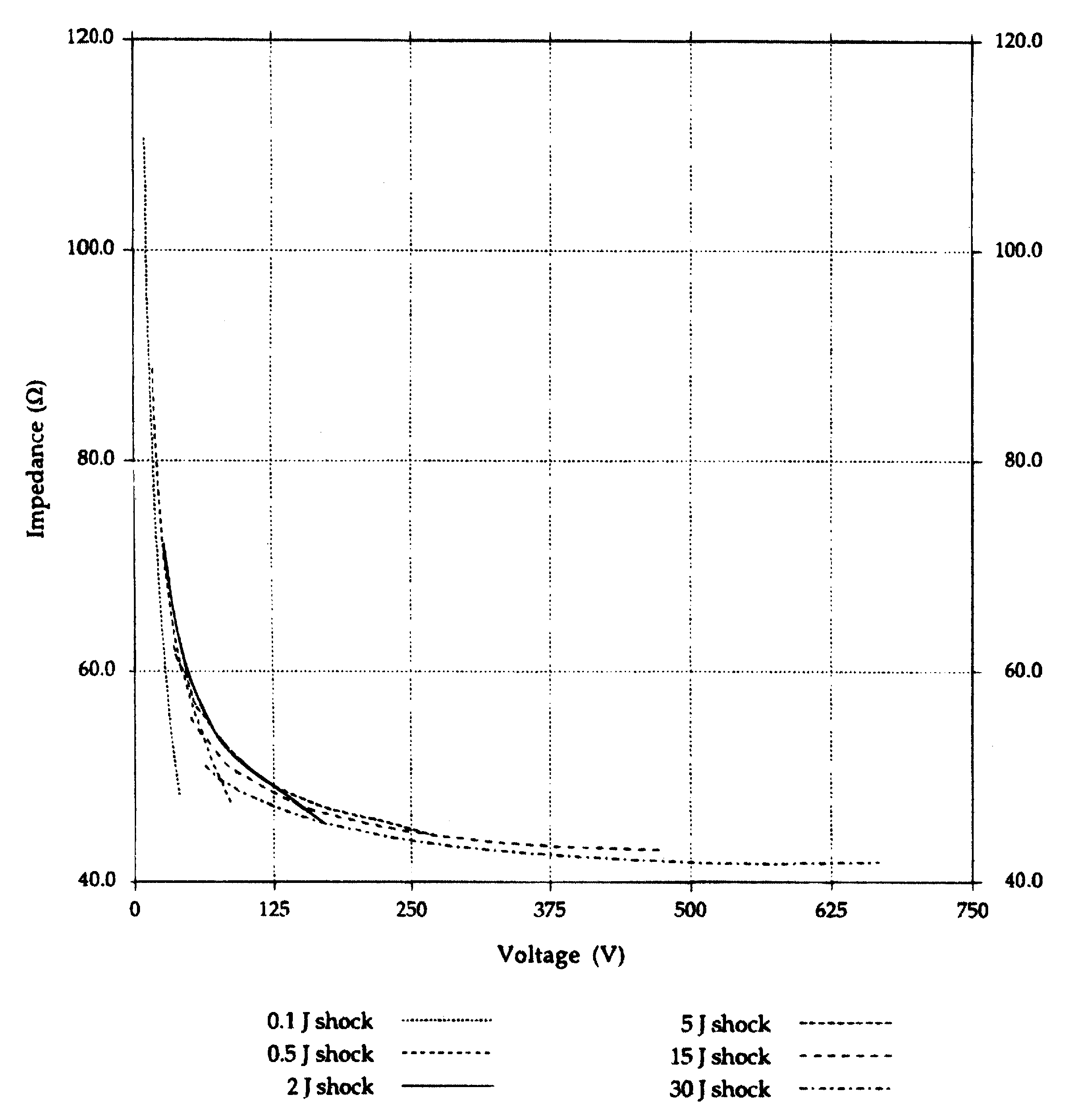
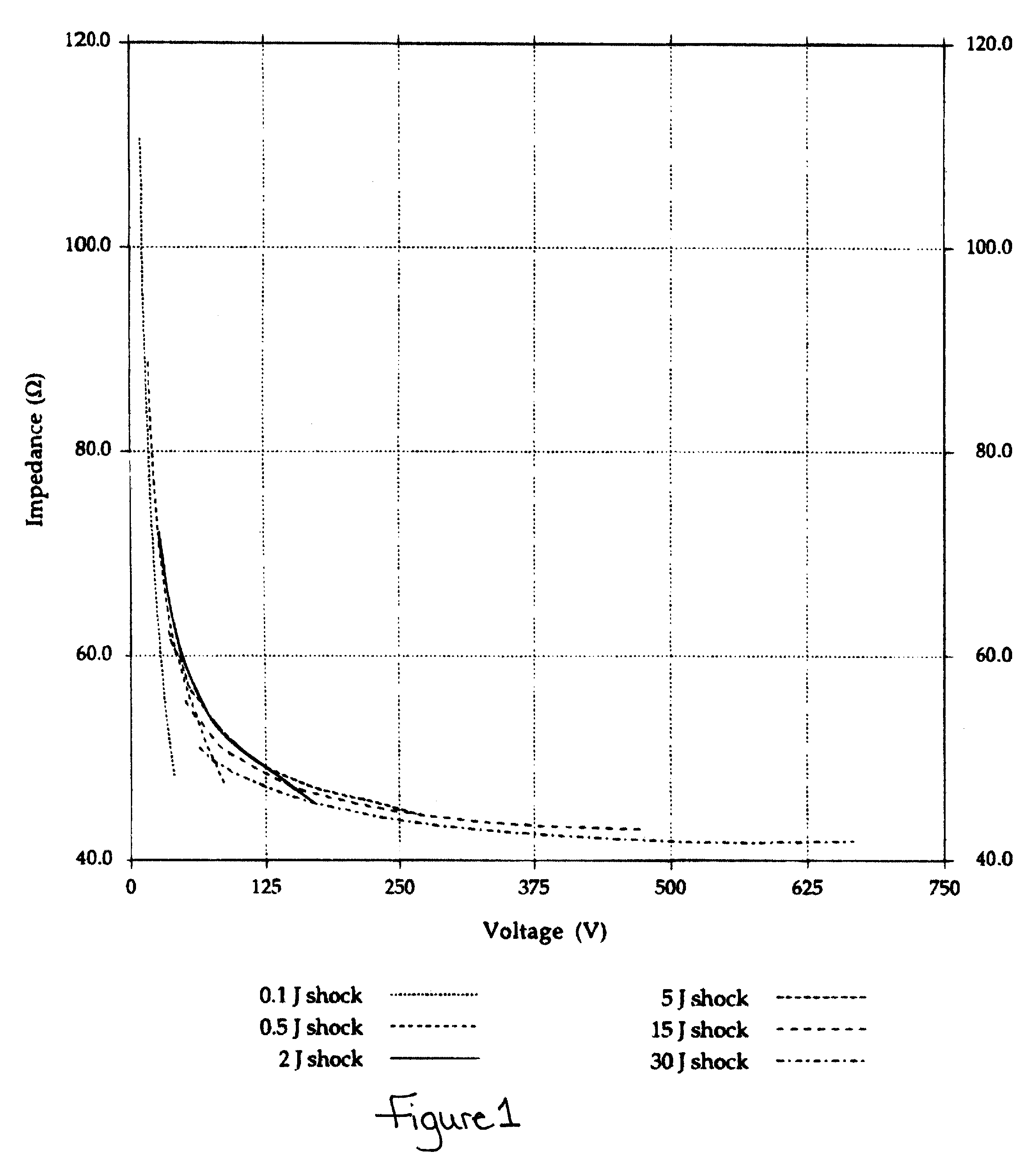
[0028]As seen in FIG. 1 the measured impedance is highly dependent on the impressed voltage and the current used. The following calculation yields the voltage required to obtain a 10% error in the impedance. As also shown in FIG. 1, the measured impedance for a typical defibrillation electrode system is giving by:

Z=41+(960 / V)−(2041 / (V^2))

where V is the impressed voltage. For larger voltages the last term is insignificant. Thus the measured impedance can be estimated by:

Z=41+(960 / V)

where the actual (high voltage) impedance was 39.4Ω. Thus, to calculate the voltage for a 10% error (approximately 4 ohms), set:

4+39.4Ω=43.4=41+(960 / V)

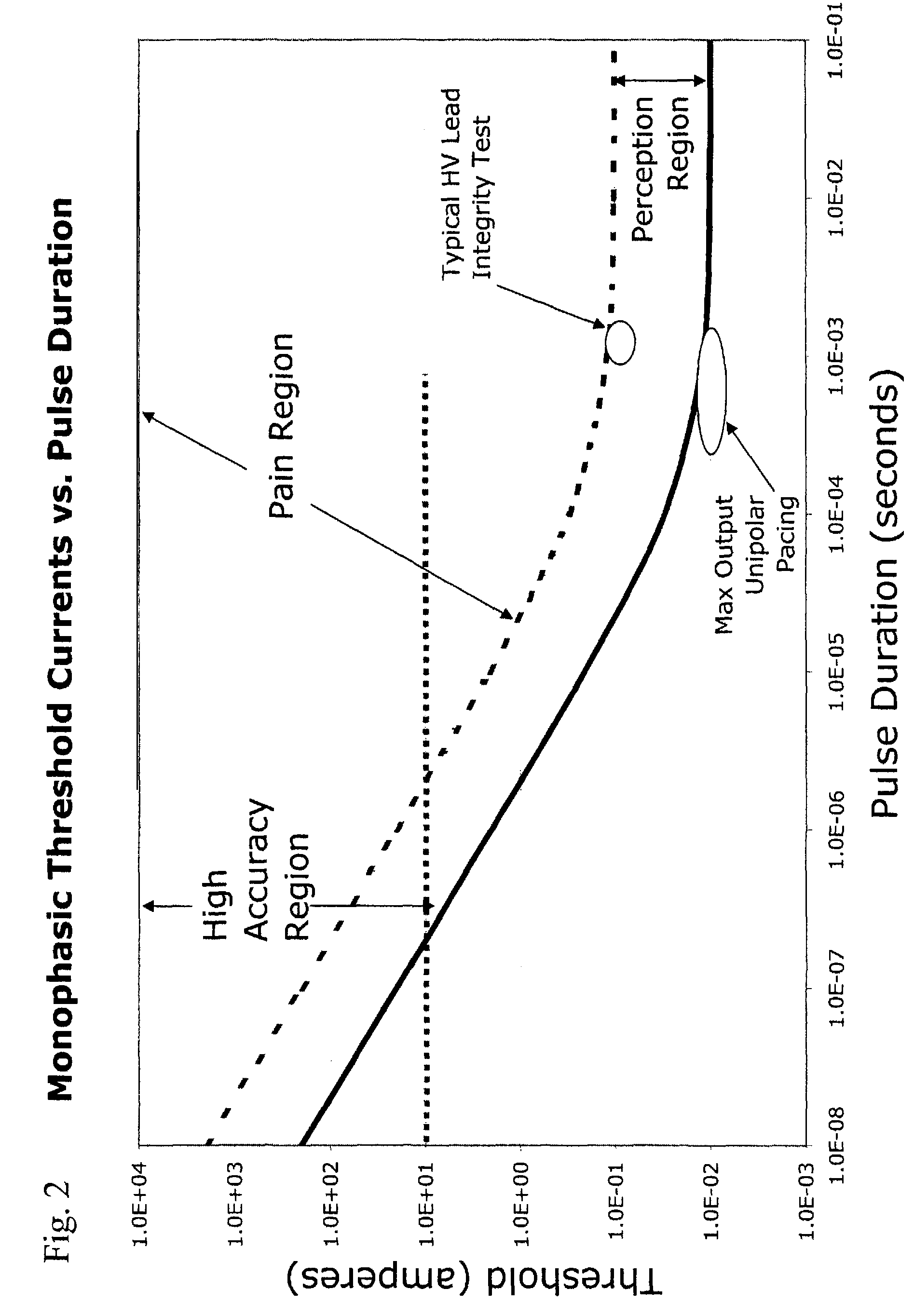
[0029]which reduces to 2.4=(960 / V), yielding a value for V of 400 volts. For the impedance of 40Ω, this equates to a required current of ten amperes which would be extremely painful to a conscious person. However, as shown in FIG. 2, even test pulses of one ampere can give significant accuracies beyond that seen with conventional approaches at lower current ...


PUM


Abstract

Methods and apparatus for accurately and painlessly measuring the impedance between defibrillation electrodes implanted in a patient utilize a high current test pulse delivered with a sufficiently high current to produce an accurate measurement of the defibrillation electrode impedance while limiting the duration of the test pulse such that the pain sensing cells in the patient do not perceive the test pulse. In one embodiment, the test pulse is generated from the high voltage transformer without storing energy in the high voltage capacitors and is delivered to the defibrillation electrodes in the patient utilizing the high voltage switching circuitry.

Description

CROSS-REFERENCE TO RELATED CASES[0001]This application claims the benefit of and priority to U.S. Provisional Patent Application No. 60 / 999,041 filed on Oct. 15, 2007, now expired, the disclosure of which is hereby incorporate by reference.FIELD OF THE INVENTION[0002]The present invention relates generally to improvements for implantable medical devices such as devices for delivering defibrillation current to a body. More particularly, the invention relates to an implantable medical device that determines the impedance between defibrillation electrodes without causing pain to the body.BACKGROUND[0003]Implantable cardioverter-defibrillators (ICDs) are used to provide various types of therapy to a cardiac patient, including, for example cardioversion and / or defibrillation. These devices consist of a hermetic housing implanted into a patient and connected to at least one defibrillation electrode and with at least one other electrode e.g., a patch-type electrode, a housing- or can-based...

Claims


Application Information

Patent Timeline
Patent Type & Authority Patents(United States)
IPC IPC(8): A61N1/00A61B5/05A61B5/00
CPCA61N1/3931A61N1/3937A61N1/3956A61N2001/083
Inventor KROLL, MARK
Owner KROLL MARK
Why Eureka
Try Eureka