
Switchable dual-band filter

a dual-band filter and switchable technology, applied in the field of switchable dual-band rf filters, can solve the problems of requiring a large circuit area and more elements, requiring a large filter circuitry, so as to achieve a small tunable range of operating passbands, reduce the effect of circuit area and small circuit area

Active Publication Date: 2008-06-10
IND TECH RES INST
View PDF7 Cites 11 Cited by
  • Summary
  • Abstract
  • Description
  • Claims
  • Application Information

AI Technical Summary

Benefits of technology

The solution achieves a compact filter design with proper impedance matching at both operating frequencies, reducing the overall size and circuit complexity while maintaining effective filtering performance.

Problems solved by technology

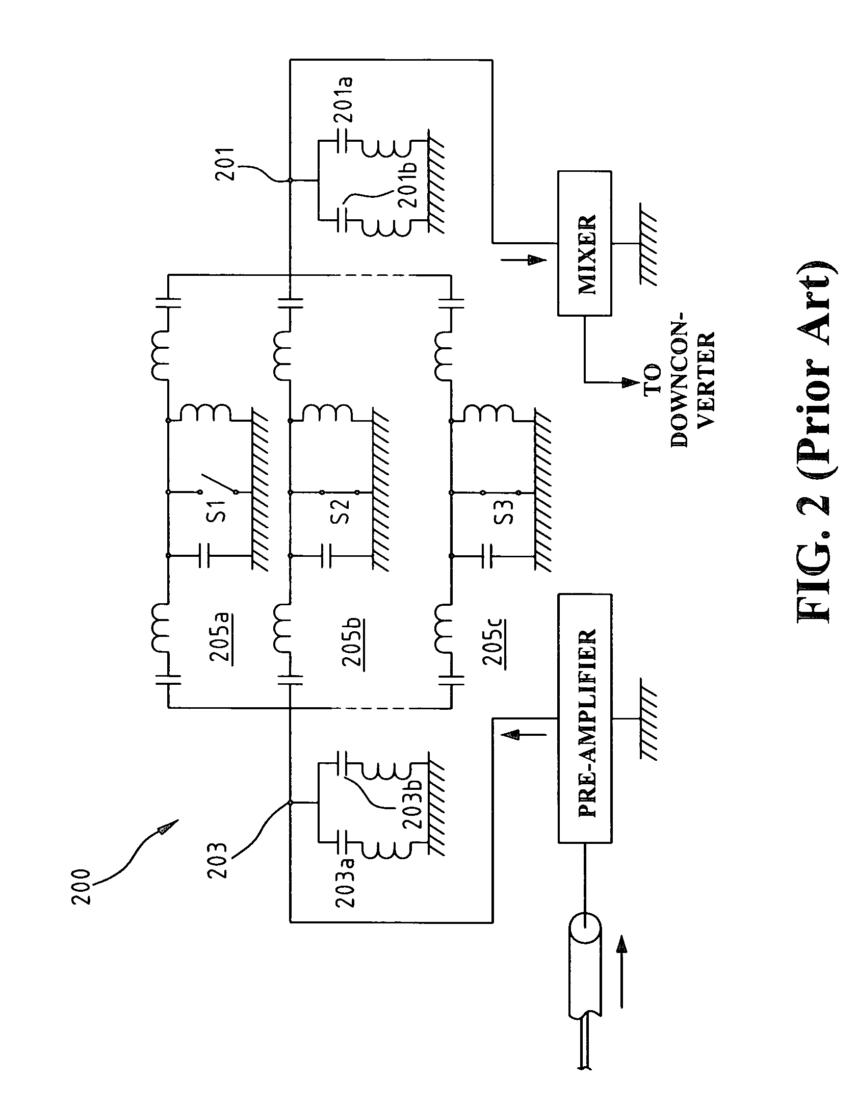
However, because each switched passband requires a filter and two switching circuits, this design has the drawbacks of requiring a larger circuit area and more elements.
However, as a filter section is required for each passband, this filter still requires a large filter circuitry.
However, the drawback of this filter is that the tunable range of operating passbands is small.
Another obstacle to overcome for the tunable or switchable filter is the matching between the output / input terminals and a resonator element when the resonance frequency of the resonator element has a drastic change.
This causes a major problem as the filter usually fails to have good matching when the two resonance frequencies have a large difference.

Method used


Image

  • Switchable dual-band filter
  • Switchable dual-band filter
  • Switchable dual-band filter

Examples


Embodiment Construction

[0024]FIG. 4 shows a simplified block diagram of a dual band RF front-end circuit according to a first embodiment of the present invention. Referring to FIG. 4, the dual band RF front-end circuit of the present invention includes two antennas, 401a corresponding to a first frequency and 401b corresponding to a second frequency, a band switch bandpass filter (BPF) 403, a band switch balun 404, a band switch low-pass filter (LPF) 405, a dual band receiver / transmitter switch 402 with two output terminals respectively connected to the band switch BPF 403 and the band switch LPF 405, and a dual-band / dual-mode transceiver chip 406 with a receiving terminal RX and a transmitting terminal TX. The receiving terminal RX is connected to the band switch BPF 403, while the transmitting terminal TX is connected to the band switch balun 404. The receiver / transmitter switch 402 is also connected to antennas 401a and 401b to determine which antenna is used to transmit or receive the signals of selec...


PUM


Abstract

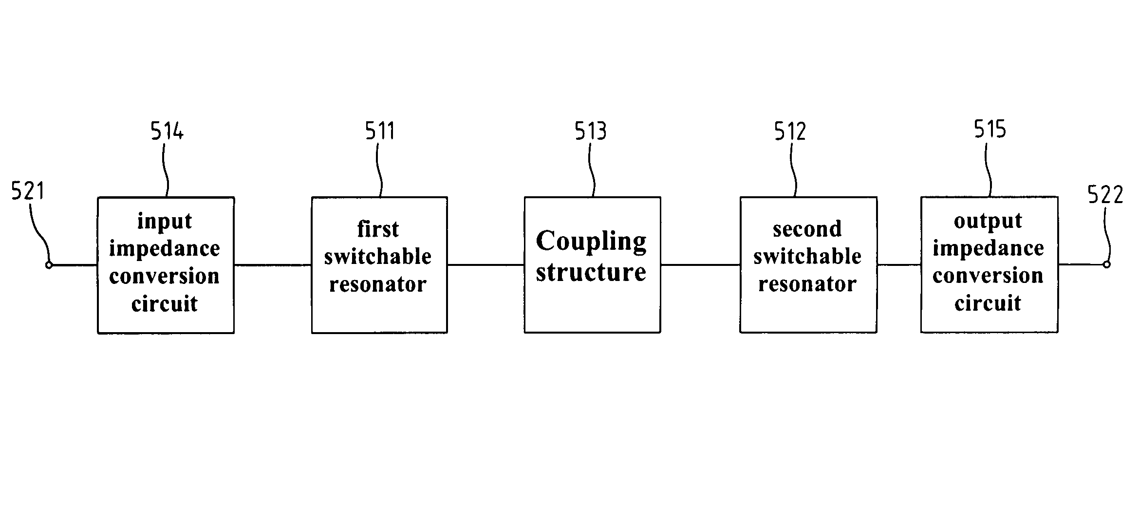
A switchable dual-band filter comprises first and second switchable resonators, a coupling structure having two ends respectively connecting the first and the second switchable resonators, an input impedance conversion circuit connecting an input terminal and the first resonator, and an output impedance conversion circuit connecting an output terminal and the second resonator. The coupling structure couples the first resonator to the second resonator, and vice versa. The input / output impedance conversion circuit converts the impedance on the input / output terminal into two distinct impedances that correspond to a first and a second operating frequency. The filter is simple in structure, occupies a smaller circuit area, and is cost-effective in manufacturing. The impedance at both operating passbands can also be matched properly.

Description

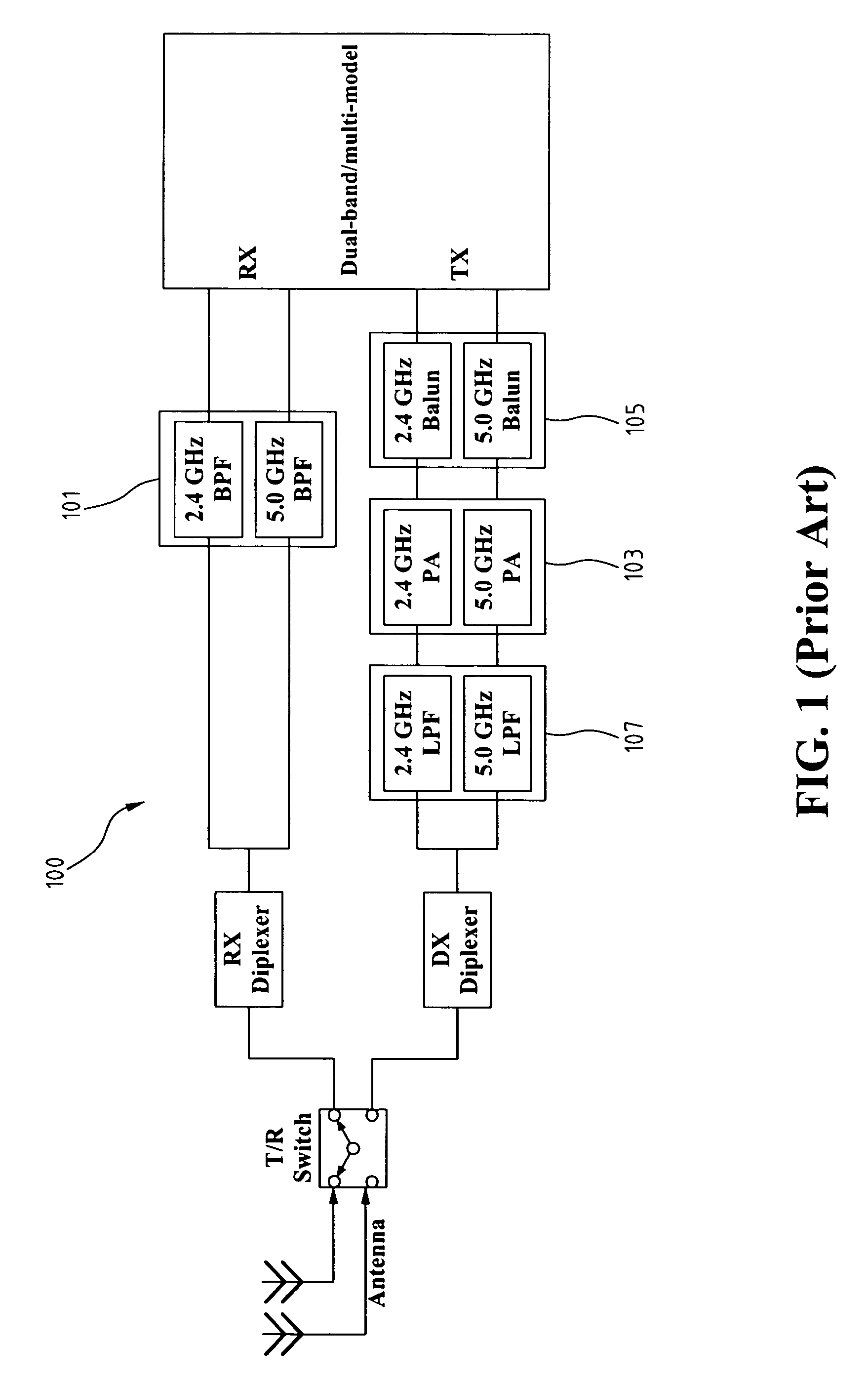
FIELD OF THE INVENTION[0001]The present invention generally relates to a radio frequency (RF) filter, and more specifically to a switchable dual-band RF filter.BACKGROUND OF THE INVENTION[0002]The trend of wireless local area network (WLAN) and mobile communication moves towards the multi-band / multi-modal system integration, for example, the WLAN 802.a, 802.b, 802.g system. The conventional dual-band RF transceiver device usually includes plural independent transceivers, and each independent transceiver is used for the signals with an individual frequency band. In the front end of the RF system, the research in demands aims at integrating RF components operating at different frequency band.[0003]FIG. 1 shows a schematic diagram of a prior-art dual-band RF front end. As shown in FIG. 1, a complete dual-band RF front end 100 includes a bandpass filter (BPF) element 101, a balun element 105, a power amplifier (PA) element 103, and a low-pass filter (LPF) element 107. Each element has t...

Claims


Application Information

Patent Timeline
Patent Type & Authority Patents(United States)
IPC IPC(8): H03H7/01
CPCH03H7/46H03H2007/386H03H2250/00
Inventor CHEN, CHENG-CHUNG
Owner IND TECH RES INST
Learn More