Methods for the protection of a thermal barrier coating system and methods for the renewal of such a protection

a technology of thermal barrier coating and protection method, which is applied in the direction of steam regeneration, non-positive displacement fluid engine, liquid fuel engine components, etc., can solve the problems of contaminants infiltrating pores, inducing mechanical stress, and affecting the lifetime of the tbc system, so as to improve the protection of the thermal barrier coating system

Active Publication Date: 2013-01-22
ANSALDO ENERGIA SWITZERLAND AG
View PDF10 Cites 28 Cited by
  • Summary
  • Abstract
  • Description
  • Claims
  • Application Information

AI Technical Summary

Benefits of technology

[0017]One of numerous aspects of the present invention includes a method which allows to assuring improved protection of thermal barrier coating systems (inclusive of bond coat) and base metal by providing a barrier, in particular a physical barrier and / or a chemical barrier onto the thermal barrier coating and / or at least partially within the porosity of the thermal barrier coating being used in a hostile environment, such as in a gas turbine operating under crude or heavy oil, with possible sand infiltration, in engines. Another aspect includes a method which allows the easy and regular renewal of such a protection.

Problems solved by technology

In the case of operation under extreme conditions (e.g., crude oil, heavy oil, presence of sand, sea water, etc.), porosity (and cracks) can be detrimental to the lifetime of the TBC system.
Contaminants can infiltrate and diffuse into pores (and cracks), potentially inducing mechanical stresses and / or reaction with the TBC and / or with the bond coat (BC) and / or with the thermally grown oxide (TGO) layer.
As a result, TBC spallation and / or bond coat corrosion may occur.
Especially in the case of an APS (atmospheric plasma spraying) deposited layer, the horizontal fine pores are difficult to infiltrate.
Since sacrificial coatings are consumed due to reaction, their durability is clearly an issue.
Under extreme conditions, such as for operation under crude or heavy oils with possible sand infiltration, erosion tremendously affects coatings.
In general, all sealants mentioned above tend to have a reduced thermal cycling resistance and a reduced total lifetime mainly due to the decreased strain tolerance of the system.
Thus, the benefit of sealing against contaminants is generally only temporary and insufficient to withstand one complete operation interval.
In consequence, the state-of-the-art protections are degraded very fast and the available technologies have not proved to perform to expectations.
This means that, for the contaminantspresent in these processes, the physical barrier is essentiallyimpermeable, which however does not necessarily meanthat it is fully dense.
A general issue is that erosion and other effects occur generally in engines and remove or degrade the physical and chemical barriers rather rapidly.
Another issue is additionally specific to the chemical barrier type of protection.
However, a thick layer is not desired since the strain tolerance of the system is concomitantly reduced.
Consequently, according to the state-of-the-art, a rather unfortunate compromise as concerns the layer thickness has to be made in order to balance the strain tolerance and the early consumption of the layer.
In fact, in practice such a compromise cannot be achieved and the protection does not survive the time of an operation interval (especially for strongly exposed areas).

Method used


Image

  • Methods for the protection of a thermal barrier coating system and methods for the renewal of such a protection
  • Methods for the protection of a thermal barrier coating system and methods for the renewal of such a protection
  • Methods for the protection of a thermal barrier coating system and methods for the renewal of such a protection

Examples


first embodiment

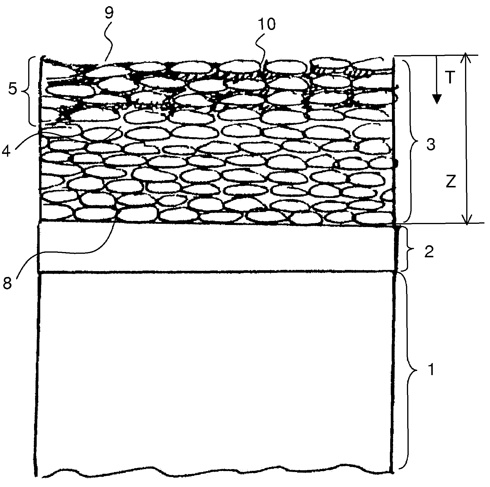
[0087]FIG. 1 shows a thermal barrier coating system to which the proposed method has been applied.

[0088]During a washing cycle, after the turbine washing using conventional liquid for the washing, a sealing substance is applied to the thermal barrier coating 3. For the application of the sealing substance, the conventional washing equipment of the engine is preferably used for the introduction of the liquid substance into the hot gas path of the engine. Thus, the sealing substance partially infiltrates into the porous structure 4 of the thermal barrier coating 3 and remains within pores of the porous structure 4. This is shown in the drawing figure by the infiltrated area 5. Another part forms a layer on top of the thermal barrier coating. The sealing substance in this way provides an essentially impermeable layer 10 within and on the thermal barrier coating 3.

[0089]Typically, not the whole thickness Z of the thermal barrier coating layer is infiltrated by the sealing substance, but...

second embodiment

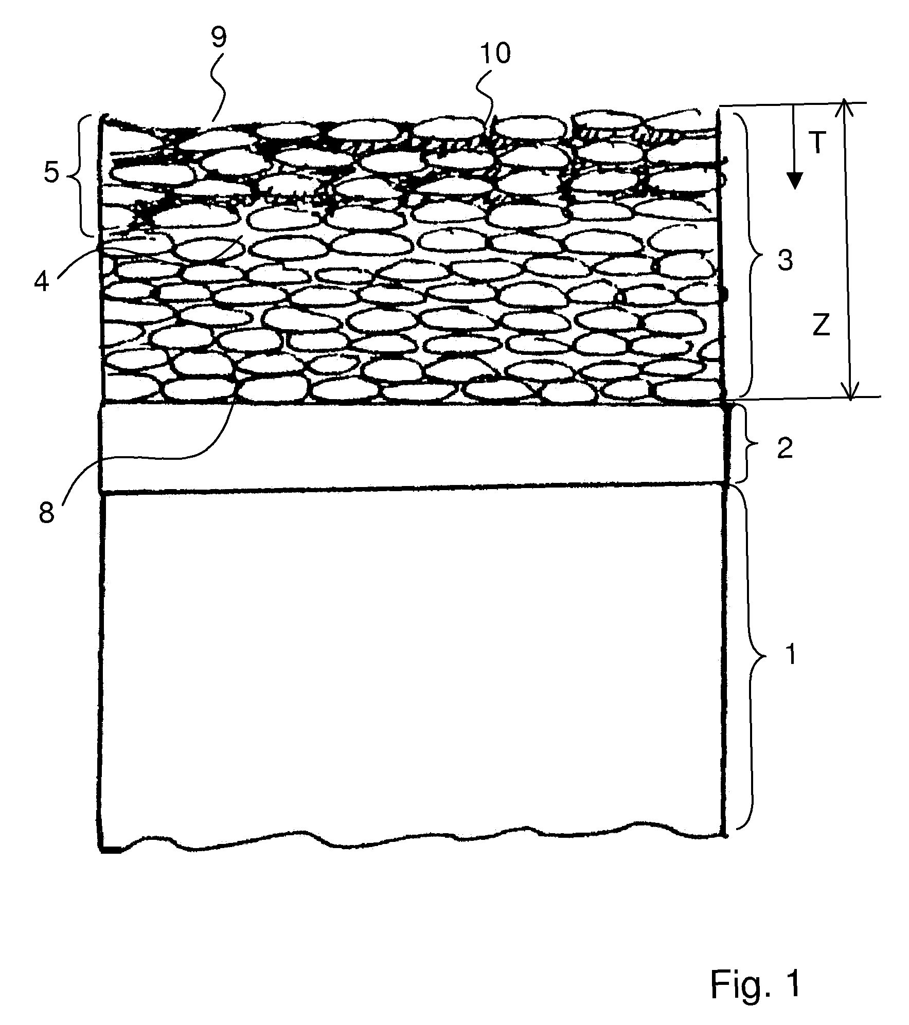
[0100]In the second embodiment the sealing or reactive substance which provides the impermeable layer 10 is applied such that it only marginally infiltrates the pores 4 adjacent to the upper surface 9 in order to provide a top coat 6 as an impermeable layer, i.e., a physical or chemical barrier. The substance can also be chemically reactive with the contaminants, forming a chemical barrier. The top layer 6 is substantially arranged on the upper surface 9 such that it extends over the upper surface 9 and only partly into the thermal barrier coating 3. Preferably in this case the top layer 6 forms a continuous layer completely covering the relevant surface of the thermal barrier coating layer.

[0101]The measure by which the sealing and / or reactive substances extend over the upper surface 9 (layer thickness essentially formed by sealing substance only) is illustrated by reference sign S. Preferably S is between 2% and 25%, in particular between 2% and 15%, of the thickness Z of the ther...

fourth embodiment

[0105]FIG. 4 shows the present invention. In this embodiment the reactive substances 7 are anchored at the surface of the TBC and provide a chemical barrier to contaminants. The reactive substances are applied to the thermal barrier coating in essentially the same manner as described above.

[0106]The reactive substances are chosen such that they are reactive versus contaminants, in particular versus contaminants from crude or heavy oils and are able to immobilize them, preventing their penetration into the thermal barrier coating layer.

[0107]As the protective species are reactive they should be renewed frequently before the end of an operational interval.

[0108]The further embodiments as given in FIG. 5-7 essentially result from a combination of the first three embodiment as illustrated in FIGS. 1-3 with an anchoring of reactive species on the surface of the layer in accordance with the embodiment as illustrated in FIG. 4. These embodiments serve to show that the different possibiliti...


PUM

PropertyMeasurementUnit
temperatureaaaaaaaaaa
viscosityaaaaaaaaaa
viscosityaaaaaaaaaa

Abstract

A method for the application and / or renewal of a protection for a thermal barrier coating system of a heat engine involves a thermal barrier coating system that includes a bond coat layer (2) and a thermal barrier coating layer (3) of porous structure (4), wherein the bond coat layer (2) is located between and in contact with a base metal (1) of a heat engine component and with the thermal barrier coating layer (3) and bonds the thermal barrier coating layer (3) to the base metal (1). At least one substance is applied inside the engine as a liquid or carried by a liquid by spraying and / or by flowing it across a hot gas exposed surface (9) of the barrier coating layer (3) of the heat engine component mounted within the heat engine in the assembled state prior to the initial start-up of the engine, before the first operation interval, or during a washing cycle of the thermal engine and / or at the end of an operation interval, before a subsequent operation interval, wherein the substance covers and / or at least partly penetrates into the porous structure (4), and concomitantly or subsequently hardens to remain within the pores (4) and / or on the upper surface (9) of the thermal barrier coating layer. Preferably, but not necessarily, for the application, the turbine washing equipment of the engine is used.

Description

[0001]This application claims priority under 35 U.S.C. §119 to European application no. 09 156 358.5, filed 26 Mar. 2009, the entirety of which is incorporated by reference herein.BACKGROUND[0002]1. Field of Endeavor[0003]The present invention relates to a method for assuring a durable (i.e., essentially during the complete operation interval) protection of thermal barrier coating systems and base metal parts of gas turbines and other heat engines, in particular from the deleterious effect of environmental contaminants present in the gas flow. In particular, the invention relates to a method of applying a protection on the ceramic surface and of renewing this protection regularly on-site.[0004]2. Brief Description of the Related Art[0005]Thermal barrier coatings (TBC) are commonly deposited onto parts of gas turbines and other heat engines in order to reduce the heat flow on the base metal. Materials such as Y-stabilized zirconia (YSZ) are frequently chosen for their intrinsically l...

Claims


Application Information

Patent Timeline
Patent Type & Authority Patents(United States)
IPC IPC(8): F01K13/02F01D1/02
CPCC23C4/18C23C26/00C23C28/00C23C28/30F05B2230/90Y10T428/31678
Inventor DUVAL, SOPHIEGRASSO, PIERO-DANIELESTANKOWSKI, ALEXANDER
Owner ANSALDO ENERGIA SWITZERLAND AG
Why Eureka
Try Eureka