Mechanical seal sliding member, and mechanical seal

a sliding member and mechanical seal technology, applied in the field of sliding members, can solve the problems of the more severe sliding condition of the mechanical seal, and achieve the effect of mechanical

Active Publication Date: 2013-01-29
EAGLE INDS +1
View PDF13 Cites 10 Cited by
  • Summary
  • Abstract
  • Description
  • Claims
  • Application Information

AI Technical Summary

Benefits of technology

[0036]In such a mechanical seal, due to the structure formed on the sliding surface of any one of the stationary sliding member or the rotary sliding member as the grating sections, it is preferably ava

Problems solved by technology

However, in recent years, sliding condition of the mechanical seal becomes more severe, many propos

Method used


Image

  • Mechanical seal sliding member, and mechanical seal
  • Mechanical seal sliding member, and mechanical seal
  • Mechanical seal sliding member, and mechanical seal

Examples


embodiments

[0071]Below, a concrete example of a mechanical seal sliding member as an embodiment of the present invention and measuring results of the characteristics such as the coefficient of friction and the like of the mechanical seal sliding member, are described.

[0072]Initially, a testing machine used for measuring the characteristics of the mechanical seal sliding member is specified.

[0073]FIG. 3 is a cross sectional view of a mechanical seal type testing machine used for a test of the mechanical seal sliding member according to the present invention.

[0074]As shown in FIG. 3, a cylindrical housing 20 is provided at a center portion in a testing machine 10 for a sliding member. A stationary sliding member 11 is mounted by engaging with tightly sealing contact via an O-ring 11 to a mounting surface provided at an object fluid chamber 20A of the housing 20. Also, a rotary sliding member 12 is retained by a retaining device 13 provided around a rotary shaft 15, in which the rotary sliding me...

example 1

1. Example 1

[0111]As an example 1, a mechanical seal sliding member having mirror finished sliding surface was used for a stationary sliding member, and a mechanical seal sliding member having sliding surface wherein a plurality of grating sections (periodic structure) consisting of a plurality of linear shape ridge portions were formed in a plurality of divided sections by femtosecond laser after mirror finish, was used for a rotary sliding member.

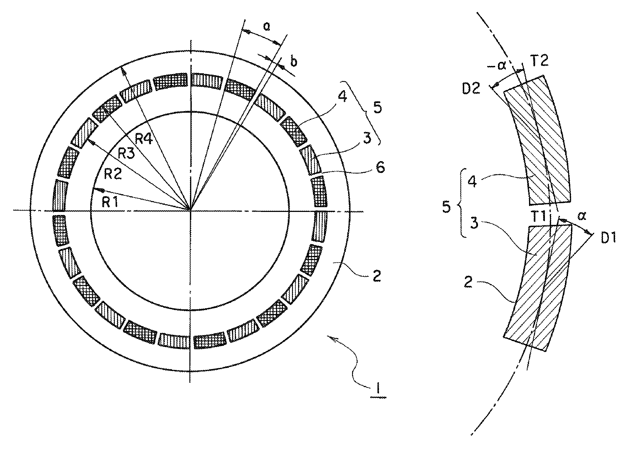
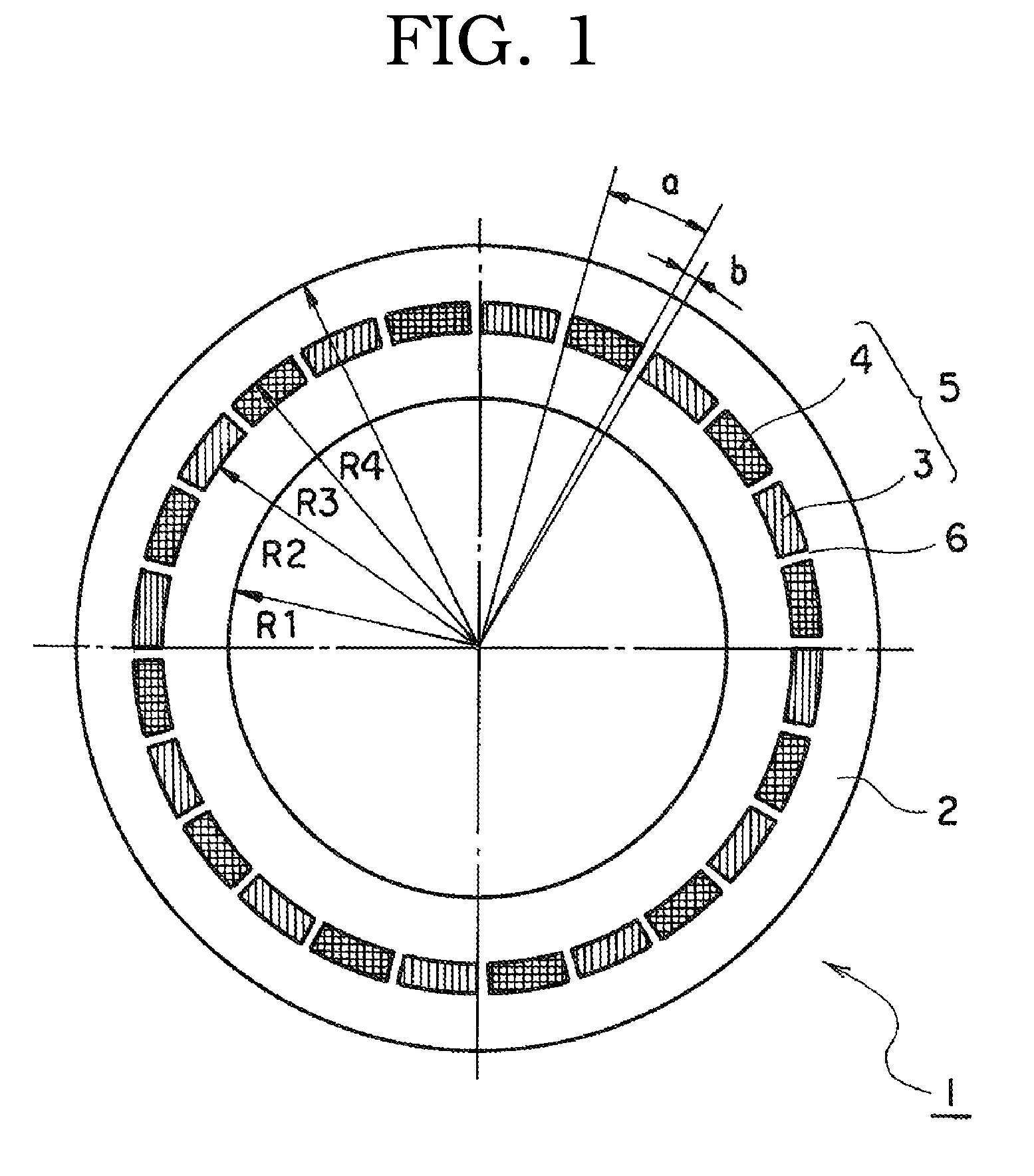
[0112]The plurality of gratings of the stationary sliding member were provided along a circumferential direction so as to be separated from each other but so as not to arranged on the inner diameter of the sliding surface. Concretely, the grating sections were formed so that a region in a radius direction was from φ37.5 to φ41.5, an angle region in the circumferential direction of each of the grating sections was 12°, and an angle region in the circumferential direction of each of non-processed sections which were spaces between the grati...

example 2

2. Example 2

[0116]As an example 2, as similar with the example 1,

[0117]a mechanical seal sliding member having mirror finished sliding surface was used for a stationary sliding member, and a mechanical seal sliding member having sliding surface wherein a plurality of grating sections (periodic structure) consisting of a plurality of linear shape ridge portions were formed in a plurality of divided sections by femtosecond laser after mirror finish, was used for a rotary sliding member,

[0118]Also, as similar with the example 1, the plurality of gratings of the stationary sliding member were provided along a circumferential direction so as to be separated from each other but so as not to arranged on the inner diameter of the sliding surface. Concretely, the grating sections were formed so that a region in a radius direction was from φ37.5 to φ41.5, an angle region in the circumferential direction of each of the grating sections was 12°, and an angle region in the circumferential direct...


PUM


Abstract

The present invention provides a mechanical seal sliding member with high lubricating characteristics, in which the coefficient of friction and the temperature of sliding surfaces are lowered and stabilized without excessive leakage. In the mechanical seal sliding member of the present invention, on the sliding surface 2, a plurality of grating sections 5 are formed separately in each of which a plurality of linear shape ridge portions parallel to each other are formed in a predetermined region with a predetermined pitch. The linear shape ridge portions of the plurality of grating sections are formed as inclined at a predetermined angle to a sliding direction of the sliding surfaces 2. Such periodic structure can improve the lubricating characteristics for lubrication. By irradiating a linearly polarized femtosecond laser with irradiating energy adjacent to a process threshold level to a material surface, a fine periodic structure with a cycle interval comparable with a laser wavelength and with a ridge depth half or less than the laser wavelength can be formed by a self-structuring manner.

Description

FIELD[0001]The present invention relates to a sliding member of a mechanical seal for a rotating shaft in a pump and the like, in particular, to a sliding member of a mechanical seal which is available to improve lubricating characteristics such as lowering and stabilizing the coefficient of friction and the temperature of a sliding surface. Also, the present invention relates to a mechanical seal using the same.BACKGROUND[0002]As materials used for sliding members (rings) of mechanical seals include a variety of combinations of silicon carbide sintered bodies, carbon bodies, cemented carbide bodies, alumina sintered bodies and the like.[0003]When sliding members made of combinations of silicon carbide bodies and another silicon carbide bodies enable use at higher PV limiting value, a high PV limit enables an increased performance and miniaturization of the sealing device and the apparatus using same. Further, combinations of two silicon carbide sliding members are frequently used w...

Claims


Application Information

Patent Timeline
IPC IPC(8): F16J15/34
CPCF16J15/3424
Inventor TESHIMA, YOSHIHIROSAWADA, HIROSHI
Owner EAGLE INDS
Why Eureka
Try Eureka