Magnetic advanced generation jet electric turbine

a jet engine and advanced technology, applied in the field of hybrid engines, can solve the problems of reducing performance, reducing horsepower, and reducing thrust to weight ratio, so as to increase horsepower, reduce weight, and reduce weight

Active Publication Date: 2013-02-05
SONIC BLUE AEROSPACE
View PDF9 Cites 43 Cited by
  • Summary
  • Abstract
  • Description
  • Claims
  • Application Information

AI Technical Summary

Benefits of technology

[0009]The Supersonic Magnetic Advanced Generation Jet Electric Turbine (S-MAGJET) described herein, and a subsonic derivative, MAGJET, integrate a gas power turbine, superconducting electric power and propulsion generation, and magnetic power flux field systems along with an ion plasma annular injection combustor which utilizes alternative petroleum-based fuel and combustion cycles to create a hybrid turbine turbomachine for aerospace propulsion. The propulsion unit is able to achieve a dramatic increase in horsepower, combustion and propulsion efficiency, and weight reduction. In addition, the turbomachinery structures may be disposed within an exo-skeleton architecture that achieves an increase in thrust to weight ratio with a concomitant increase in fuel efficiency and power generation over traditional gas turbine technology today. The S-MAGJET can provide a flight operation envelope with little or no off-design flight condition. The engine continuously adjusts the temperature, pressure and mass airflow requirements using an electromagnetic power management system architecture. With this system architecture, the engine performance may be controlled across the entire desired flight envelope, whether subsonic, transonic or supersonic flight conditions. With bypass fan(s), compressor stages and turbine segments controlled electrically in a shaftless turbine design, the S-MAGJET maximizes the propulsion efficiencies over a broader range of operating conditions compared to current art of turbine technology and at much higher thermodynamic and aerodynamic efficiencies.
[0012]In the engine described herein, the electrical generation is provided by superconducting ring generators that are powered by the high velocity exhaust thrust from the combustor section of the engine. The bypass fan is a twin fan system in which one fan counter rotates with the other fan, which reduces aerodynamic swirl and drag. The bypass fan configuration is not constrained by a drive shaft, heavy gears and complex gear boxes, nor complex lubrication systems and it can be run at an optimal rotational speed so as to maximize its efficiency at any aircraft velocity, or altitude. The bypass fans running independently from the compressor can be run at much slower speeds than the compressor, this means a more efficient RPM for the larger diameter fan blade designs whether a low bypass fan design as in a supersonic engine or a high bypass fan design in a subsonic engine. Raising its efficiency dramatically is now possible in pushing air past the compressor core and power turbines, for thrust and the overall efficiency of the engine. Additionally, the lower operating speeds afford the use of wider blades, raising aerodynamic efficiency and thrust per horsepower, making the engine architecture greatly more efficient than the current art of engine designs. The electric compressor is designed with fewer stages than that of current turbine technology. The compressor is an axial, multi-stage design of 8 stages in a supersonic derivative, and 9 stages in a subsonic derivative of the engine technology. Three (3) low pressure stages and six (6) high pressure stages are present in the subsonic design, current art of turbines would take at least thirteen (13) compressor stages to compress a similar amount of incoming air. This is possible as each stage operates independently from one another, and can, as they are driven electrically, and each stage is more efficient. As the light weight superconducting ring motors for the compressor do not require a drive shaft, nor the bypass fans or the superconducting ring generators of the power turbine, a “hollow-core shaftless” tunnel is left in the center of the hybrid electric turbine which now carries additional bypass air. Bypass air as the major component of thrust, rather than the hot exhaust from the power turbine being utilized as thrust is a more efficient method of producing thrust for propulsion in turbines. Therefore, in S-MAGJET, the majority of electric power produced off the power turbine via the superconducting ring generators is directed forward through a proprietary electric power management system to run the electric bypass fans and the electric compressor. This electrical independence of the bypass fan from the multi-stage axial compressor raises overall efficiency of the engine. This

Problems solved by technology

In addition, the DOD and Armed Services are now demanding significant increases in electric output from turbine flight engines.
Future aircraft concepts are demanding in excess of 1.0 megawatt of power which current turbine engine companies cannot deliver off of their present engine designs, largely because they are restricted by the reduction performance of gear boxes, drive shafts and the generator added on as an additional component which is not made by the OEM engine supplier.
These systems are quite heavy and typically limit the thrust to weight ratios to not more than 7 to 1.

Method used


Image

  • Magnetic advanced generation jet electric turbine
  • Magnetic advanced generation jet electric turbine
  • Magnetic advanced generation jet electric turbine

Examples


Embodiment Construction

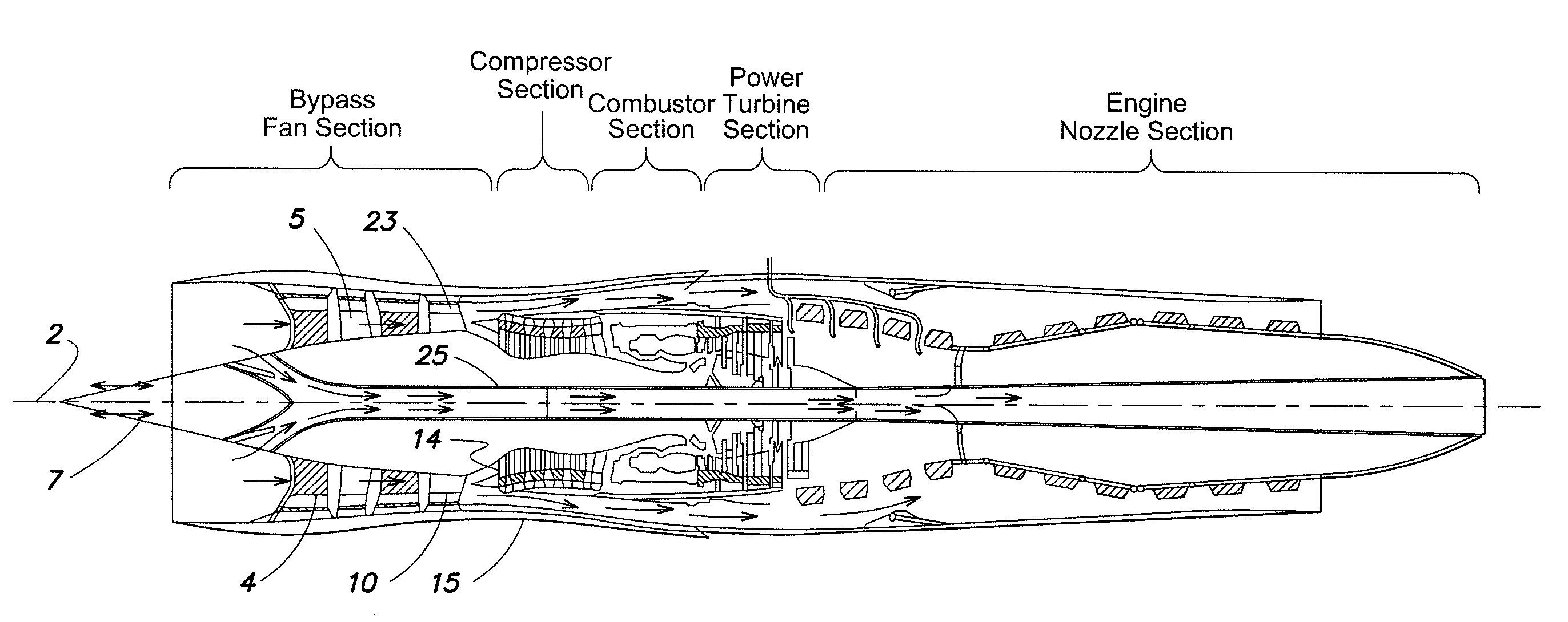
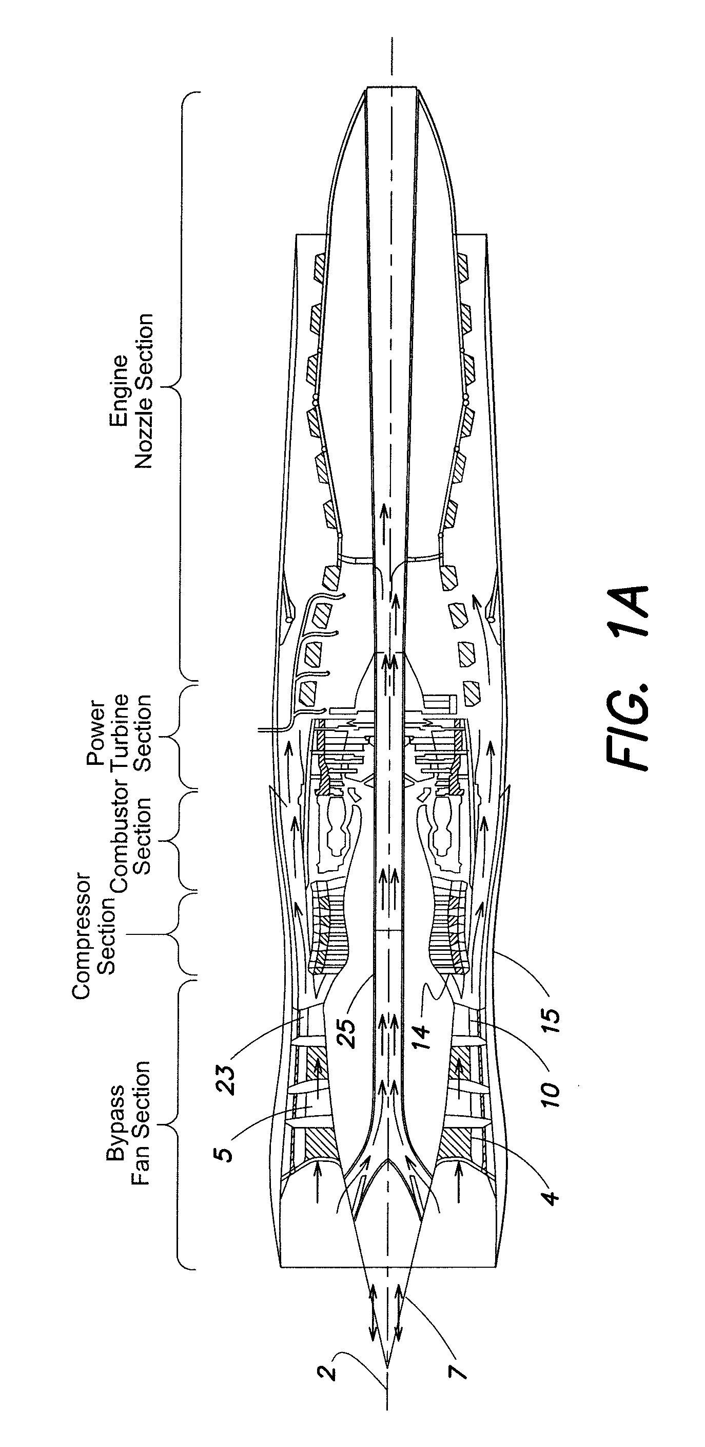
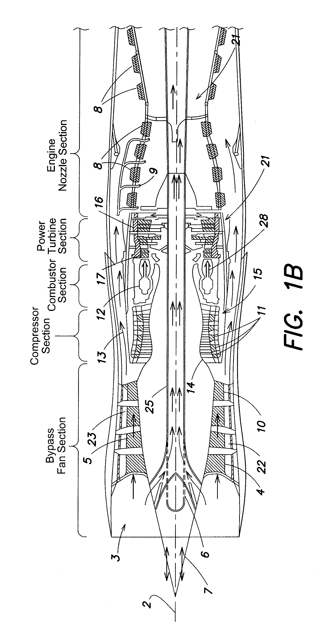
[0047]FIGS. 1A-C R. schematic representations of an aerospace supersonic aerospace gas turbine engine (1) in accordance with an exemplary embodiment comprises an outer casing or exoskeleton (15) extending the along an axial centerline axis (2). Exoskeleton (15) has a generally hollow cylindrical shape the specific dimension of which may be selected by the designer for specific parameters of high-speed flight. Exoskeleton (15) may comprise, in one embodiment an outer casing and an inner casing having a space there between. Turbine engine (1) further comprises an inlet section (3) into which air enters and is propelled in a bypass fan section (4) by the first of two counter-rotating bypass fans, after which the air is diffused and straightened through a counter-rotating diffuser (5) and further propelled by any second bypass fan (5). An aerospace ram (7) which moves in and out linearly along the axial centerline 2 and is attached to a slotted section of the bypass tunnel (6) to accomm...


PUM


Abstract

Supersonic Magnetic Advanced Generation Jet Electric Turbine (S-MAGJET) described herein, and a subsonic derivative, MAGJET, integrate a gas power turbine, superconducting electric power and propulsion generation, and magnetic power flux field systems along with an ion plasma annular injection combustor which utilizes alternative petroleum-based fuel and combustion cycles to create a hybrid turbine turbomachine for aerospace propulsion. The propulsion unit is able to achieve a dramatic increase in horsepower, combustion and propulsion efficiency, and weight reduction. In addition, the turbomachinery structures may be disposed within an exo-skeleton architecture that achieves an increase in thrust to weight ratio with a concomitant increase in fuel efficiency and power generation over traditional gas turbine technology today. The engine continuously adjusts the temperature, pressure and mass airflow requirements using an electromagnetic power management system architecture. Engine performance may be controlled across the entire desired flight envelope, whether subsonic, transonic or supersonic flight conditions.

Description

RELATED APPLICATIONS[0001]This application claims priority to co-pending, commonly owned Provisional Patent Application Ser. No. 61 / 189,365, entitled MAGNETIC ADVANCED GENERATION JET ELECTRIC TURBINE, filed Aug. 19, 2008, by inventor Richard H. Lugg, and Provisional Patent Application Ser. No. 61 / 224,666 entitled MAGNETIC ADVANCED GENERATION JET ELECTRIC TURBINE, filed Jul. 10, 2009, by inventor Richard H. Lugg.FIELD OF THE INVENTION[0002]The subject matter described herein relates generally to jet engines and more particularly to hybrid engines that generate both significant thrust and surplus electrical energy to drive other engine components.BACKGROUND OF THE INVENTION[0003]Over the past 10-20 years research has focused on increasing jet engine performance while reducing engine weight and reducing the costs associated with engine production and maintenance. In particular, government and military funded programs have focused on using ceramic components for the hot section of gas t...

Claims


Application Information

Patent Timeline
Patent Type & Authority Patents(United States)
IPC IPC(8): F02C3/00
CPCF01D15/10F02C7/32F02K1/08F02K3/025F02K3/06F02K5/00H05H1/50F02C3/04F05D2270/172F05D2300/507
Inventor LUGG, RICHARD H.
Owner SONIC BLUE AEROSPACE
Why Eureka
Try Eureka