Lithographic fabrication of general periodic structures

a general periodic structure and lithography technology, applied in the field of photolithography, can solve the problems of no gain in resolution with respect to the mask, limited resolution, and very sensitive distance distribution of the intensity distribution of the imaged pattern, and achieves a large depth of focus, a large range of applications, and a high degree of control over the intensity distribution.

Active Publication Date: 2013-02-05
EULITHA
View PDF7 Cites 20 Cited by
  • Summary
  • Abstract
  • Description
  • Claims
  • Application Information

AI Technical Summary

Benefits of technology

[0031]Advantageously also, the method includes introducing a liquid between the mask and the substrate in order to enhance the resolution of the photolithographic system.
[0034]The method of the invention allows a high degree of control over the intensity distribution in the image of the periodic pattern of features printed onto the substrate surface, in particular with respect to i) the shape of features in the plane of the substrate surface, ii) the slope of the intensity profile at the edges of the features, iii) the intensity contrast of the features, iv) higher spatial frequency of the periodic features in the printed pattern compared to that of the periodic features in the mask (or, equivalently, smaller period of the printed pattern compared to that of the periodic pattern in the mask, v) array symmetry (i.e. square, rectangular, hexagonal, “honeycomb”, etc) of the printed pattern compared to that in the mask, and vi) the depth of focus of the image. It therefore enables a considerably greater variety of periodic patterns to be printed in comparison with the prior art techniques of achromatic Talbot lithography and displacement Talbot lithography, whilst substantially retaining the major advantage of those techniques, that is, a large depth of focus for high-resolution periodic patterns. Consequently, the method of the invention allows a much greater range of applications than ATL and DTL.

Problems solved by technology

With the Talbot technique, however, the intensity distribution of the imaged pattern is very sensitive to the distance from the mask.
This limitation is especially severe if the periodic patterns need to be printed onto substrates that have imperfect flatness or have topographical features on their surface.
A major drawback of this method is that the pattern transferred to the substrate necessarily has the same period as the pattern in the mask, in other words there can be no gain in resolution with respect to the mask.
Furthermore, only one-dimensional, line / space periodic patterns can be transferred with this method, which is a considerable disadvantage.
Additionally, in order that the imaged pattern has a good contrast this method requires the use of expensive phase masks that are usually formed by etching the patterns into fused silica substrates.
Moreover, this method requires obliquely incident light which results in a rather cumbersome system configuration, and requires polarized light which can further complicate the illumination system and reduce the utilization efficiency of the light source.
This property of a stationary image is also entirely different to the behavior of the images of mask patterns produced by conventional projection, proximity or contact lithography techniques, for all of which the images show a strong variation in the direction of image propagation, thus restricting their range of application.
A drawback of ATL is that it requires a relatively large separation between the mask and substrate, and so the spatial coherence and collimation of the illumination beam need to be much higher.
For certain light sources, such as arc lamps, this is a problem because higher spatial coherence and collimation can only be achieved by greater spatial filtering, and this reduces the power in the illumination beam, which is undesirable for a production process.
Increasing the separation between mask and substrate also degrades the edges of the printed pattern.
This occurs, firstly, because of Fresnel diffraction effects at the edges of the light-field transmitted by the mask, which get stronger as the propagation distance increases; and, secondly, because the different diffracted orders in the transmitted light-field diverge as they propagate, and so at the edges of the light-field there is imperfect overlap between the orders and therefore imperfect image generation, which gets worse with increasing separation.
Using the ATL or DTL techniques (or a combination of partial forms thereof), it can be difficult and / or expensive, however, to design and realize mask patterns that can generate the intensity distributions required at the substrate surface for certain applications.
Furthermore, they are too restrictive for generating images with intensity profiles that have large enough gradients at the edges of the features and have sufficiently high contrast for ensuring a high-yield production process.

Method used


Image

  • Lithographic fabrication of general periodic structures
  • Lithographic fabrication of general periodic structures
  • Lithographic fabrication of general periodic structures

Examples


first embodiment

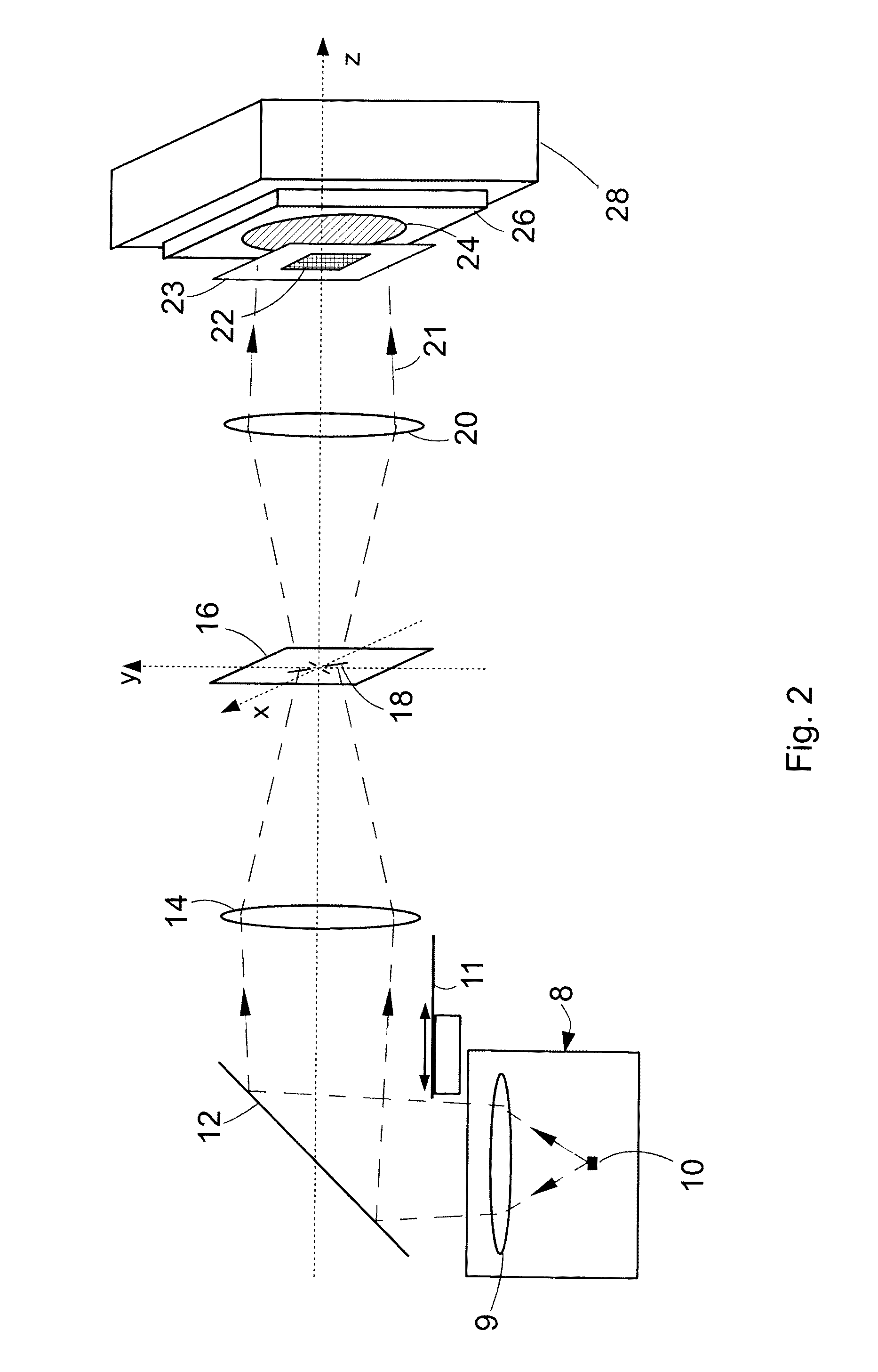
[0063]With reference to FIG. 2, which shows the present invention, a commercially available 500 W mercury-xenon arc lamp unit 8 is employed as the light source. Its generates a broad spectrum of light including a component in the deep ultra-violet (DUV). The lamp unit 8 has a condenser lens 9 with a focal length ˜50 mm that produces a 40 mm-diameter beam with good uniformity of intensity. Since the effective size of the arc 10 in the lamp unit 8 is ˜2.5 mm×2.5 mm and the arc 10 is located in the focal plane of the condenser lens 9, the range of angles of the light rays in the output beam from the lamp unit 8 is ˜±25 mR. After passing through an open electronically controlled shutter 11, the beam is incident on a dielectric mirror 12 that is highly reflective in the spectral range ˜220-260 nm and highly transmissive outside of this range. The resulting beam of DUV light with a bandwidth ˜40 nm that is reflected by this mirror 12 illuminates a lens 14 with focal length 100 mm which fo...

second embodiment

[0080]In the case of the second embodiment, exposure sequences using the discrete and continuous schemes are devised to generate the angular distributions represented by FIGS. 7a, 8a, 9a, 10a, 11a and 12a. Similarly, before illuminating with each of the angular distributions, an unexposed photoresist coated wafer 48 is loaded to the chuck 50 and positioned so that it is substantially parallel to the pattern mask 46 and separated from it by a distance of ˜60 μm. During the exposure of the wafer to each angular component, the wafer is longitudinally displaced with respect to the pattern mask by a distance of ˜7.5 μm. This value corresponds to the separation between successive Talbot planes, as determined using equ. (1) for the values of pattern period and illumination wavelength concerned, so that each angular component exposes the wafer to the entire range of lateral intensity distributions between successive Talbot planes.

[0081]The resultant, or net, image that illuminates the photo...


PUM


Abstract

A lithographic method related to Talbot imaging for printing a desired pattern of features that is periodic or quasi-periodic in at least one direction onto a substrate surface, which method includes providing a mask bearing a pattern of mask features, arranging the substrate parallel and in proximity to the mask, providing an illumination source having a central wavelength and a spectral bandwidth, forming from said source an illumination beam with an angular distribution of intensity, arranging the distance of the substrate from the mask and exposing the mask pattern to said beam so that each angular component of illumination exposes the substrate to substantially the entire range of lateral intensity distributions that occur between successive Talbot image planes for the illumination wavelengths, wherein the angular distribution of the beam is designed in conjunction with the pattern of features in the mask and the distance of the substrate from the mask.

Description

CROSS-REFERENCE TO RELATED APPLICATIONS[0001]Not ApplicableSTATEMENT REGARDING FEDERALLY SPONSORED RESEARCH OR DEVELOPMENT[0002]Not ApplicableTHE NAMES OF THE PARTIES TO A JOINT RESEARCH AGREEMENT[0003]Not ApplicableINCORPORATION BY REFERENCE OF MATERIAL SUBMITTED ON A COMPACT DISC[0004]Not ApplicableBACKGROUND TO THE INVENTION[0005]1. Field of the Invention[0006]This invention generally relates to the field of photolithography as employed for the fabrication of micro- and nano-structures, and it relates more particularly to the field of Talbot imaging as employed for transferring periodic patterns of features defined in a mask onto a photosensitive layer on a substrate.[0007]2. Description of Related Art[0008]Lithographic fabrication enables the creation of micro- and nano-patterns on surfaces. Photolithographic techniques involve exposure of a photosensitive surface to a light-field with a certain pattern of intensity distribution. The surface usually consists of a thin layer of s...

Claims


Application Information

Patent Timeline
Patent Type & Authority Patents(United States)
IPC IPC(8): G03B27/52
CPCG03B27/58G03F7/70325G03F7/7035G03F7/70408
Inventor SOLAK, HARUN H.DAIS, CHRISTIANCLUBE, FRANCIS
Owner EULITHA
Why Eureka
Try Eureka