Liquid lens and apparatus incorporating the same

a liquid lens and liquid technology, applied in the field of liquid lenses, can solve the problems of insufficient optical performance, inability to achieve predetermined refractive power, and difficulty in processing concave surfaces, etc., and achieve the effects of large change in refractive power, high sensitivity to voltage application, and high manufacturing cos

Inactive Publication Date: 2013-02-12
CANON KK
View PDF9 Cites 5 Cited by
  • Summary
  • Abstract
  • Description
  • Claims
  • Application Information

AI Technical Summary

Benefits of technology

[0016]One aspect of the present invention is directed to a liquid lens which is inexpensive to manufacture and is subject to a large change in refractive power (i.e., high in sensitivity to application of a voltage) with low driving voltage.
[0018]In the liquid lens according to the present invention, an inner wall of a vessel containing an electrolyte liquid and a non-electrolyte liquid and an end of an interface between these liquids is in contact with has varying affinity with the non-electrolyte liquid (oleophilicity) depending on the position. In particular, affinity is lower on the side of the non-electrolyte liquid than on the side of the electrolyte liquid. That is, wettability of the inner wall is more oleophobic on the side of the non-electrolyte liquid. With this configuration, it is possible to change a contact angle θ with a small variation in an applied voltage and thus to achieve a sensitive change in refractive power of the lens with low driving voltage and a small variation in the voltage.

Problems solved by technology

These two liquids typically are the same in density because a difference in density causes a distorted shape of a spherical surface of the interface due to the influence of gravity which leads to insufficient optical performance.
Patent Document 1 attempts to align the center of the droplet constituted by the insulating liquid with the central axis O of the droplet by causing “wettability” of the inner wall surface of the chamber with respect to the electrically conductive liquid to be lowered in a radial direction toward the central axis O. However, no attempt is made to achieve predetermined refractive power when a low voltage is applied.
However, in an attempt to obtain a liquid lens with a concave contact surface, regarding a section which includes a cylindrical optical axis and is parallel to the optical axis, it is necessary to provide a concave ring electrode and an insulating layer which constitute the contact surface: such a concave surface is difficult to process and sufficient accuracy is required to process the same.
Such a liquid lens is expensive to manufacture and, therefore, is difficult to be used as a liquid lens suited for mass production.

Method used


Image

  • Liquid lens and apparatus incorporating the same
  • Liquid lens and apparatus incorporating the same
  • Liquid lens and apparatus incorporating the same

Examples


second embodiment

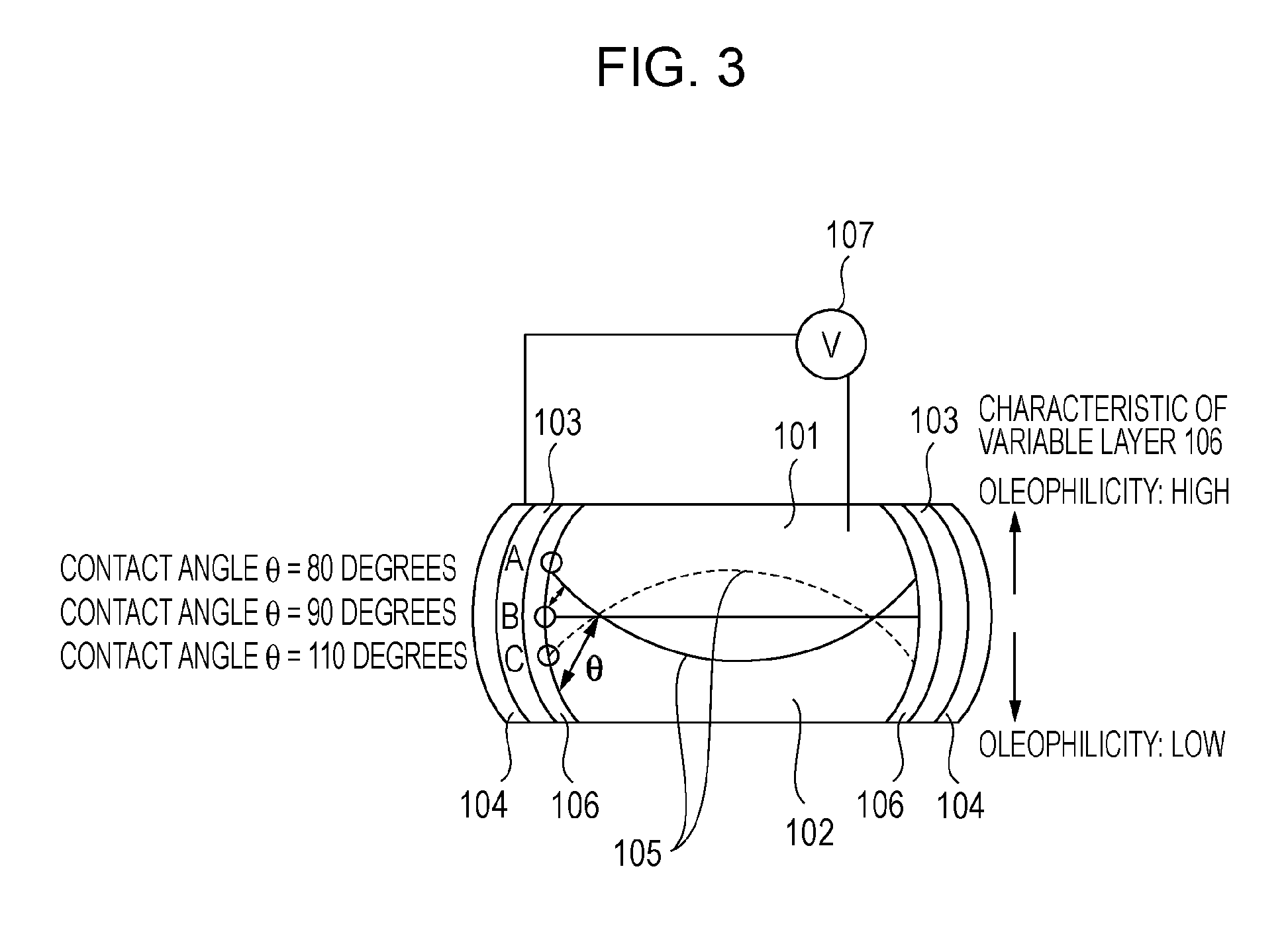
[0117]FIG. 5A is a configuration diagram of the liquid lens according to the second embodiment (with a cylindrical electrode) and FIG. 5B is a V-θ characteristic graph. A V-θ characteristic table is given in Table 3.

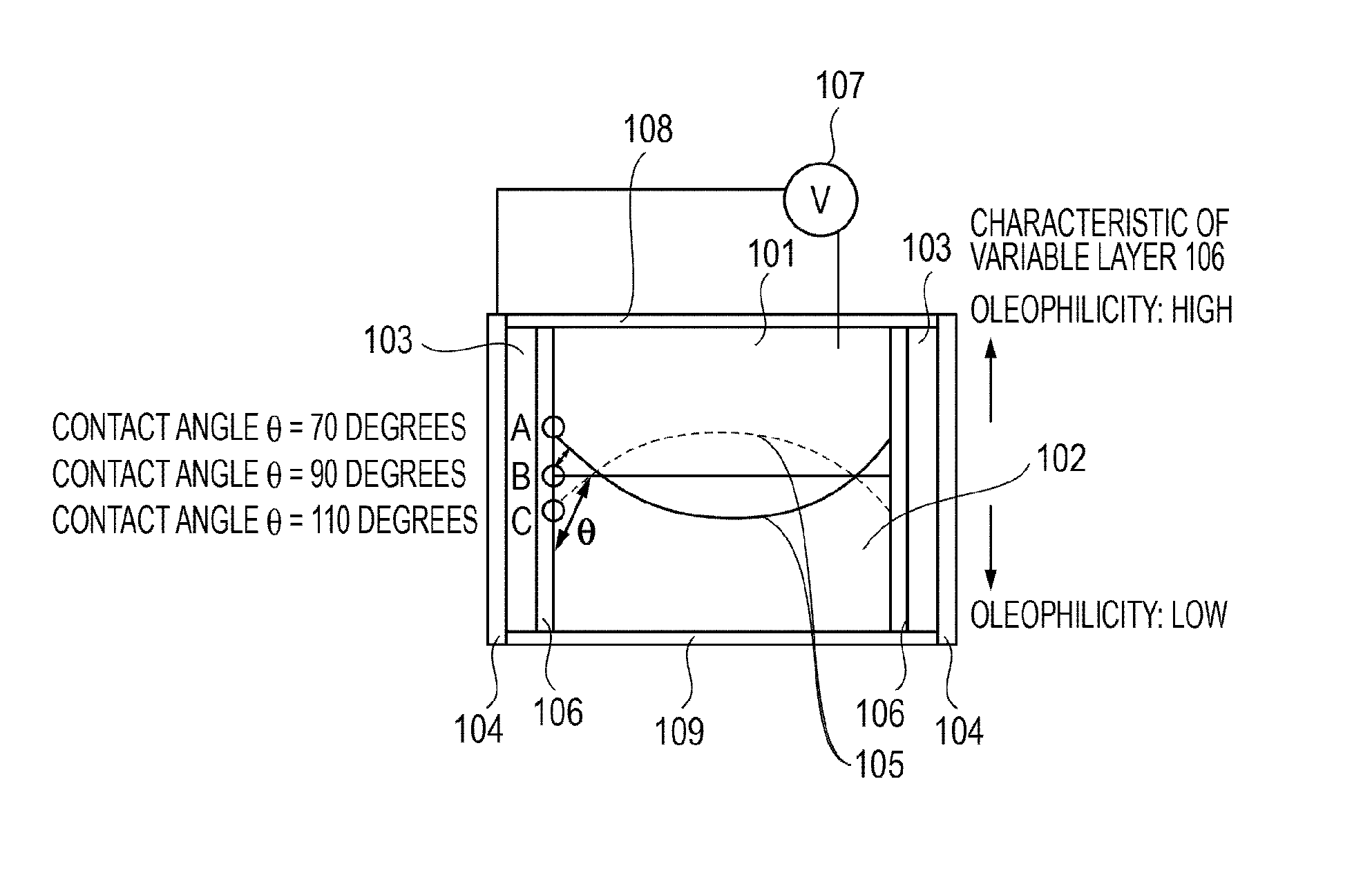
[0118]The characteristic of a θ0 variable layer 106 will be described. Wettability of the θ0 variable layer 106 when an end of the interface 105 is situated closest to the electrolyte liquid 101 is 70 degrees (i.e., the initial contact angle θ0=θ00 at V=0). Wettability of the θ0 variable layer 106 when the end of the interface 105 is situated closest to the non-electrolyte liquid 102 (i.e., the contact angle θ0=θ0max at V=0) is increased to as large as 107.5 degrees (i.e., oleophobicity is increased). Wettability of the θ0 variable layer 106 is changed linearly from 70 degrees to 107.5 degrees as represented by a θ0 curve in FIG. 5B. The thickness of the insulating layer 103 below the θ0 variable layer 106, the dielectric constant of the insulating layer 103 and the inte...

third embodiment

[0122]FIG. 6A is a configuration diagram of the liquid lens according to the third embodiment (with a cylindrical electrode) and FIG. 6B is a V-θ characteristic graph. A V-θ characteristic table is given in Table 4.

[0123]The characteristic of a θ0 variable layer 106 will be described. Wettability of the θ0 variable layer 106 when an end of the interface 105 is situated closest to the electrolyte liquid 101 is 70 degrees (i.e., the initial contact angle θ0=θ00 at V=0). Wettability of the θ0 variable layer 106 when the end of the interface 105 is situated closest to the non-electrolyte liquid 102 (i.e., the initial contact angle θ0=θ0max at V=0) is increased to as large as 115 degrees (i.e., oleophobicity is increased). Wettability of the θ0 variable layer 106 is changed linearly from 70 degrees to 115 degrees as represented by a θ0 curve in FIG. 5B. The thickness of the insulating layer 103 below the θ0 variable layer 106, the dielectric constant of the insulating layer 103 and the i...

fourth embodiment

[0128]FIG. 7A is a configuration diagram of the liquid lens according to the fourth embodiment (with a cylindrical electrode) and FIG. 7B is a V-θ characteristic graph. A V-θ characteristic table is given in Table 5.

[0129]The characteristic of a θ0 variable layer 106 will be described. Wettability of the θ0 variable layer 106 when an end of the interface 105 is situated closest to the electrolyte liquid 101 is 70 degrees (i.e., the initial contact angle θ0=θ00 at V=0). Wettability of the θ0 variable layer 106 when the end of the interface 105 is situated closest to the non-electrolyte liquid 102 (i.e., the initial contact angle θ0=θ0max at V=0) is increased to as large as 88.5 degrees (i.e., oleophobicity is increased). A change in wettability of the θ0 variable layer 106 differential monotonically increases from 70 degrees to 88.5 degrees as represented by a θ curve in FIG. 7B. The thickness of the insulating layer 103 below the θ0 variable layer 106, the dielectric constant of the...


PUM


Abstract

A liquid lens includes a vessel having an inner wall and configured to contain liquid, an electrolyte liquid and a non-electrolyte liquid forming an interface therebetween and being contained in the vessel, and a voltage applying unit which applies a voltage to the electrolyte liquid. A shape of the interface between the electrolyte liquid and the non-electrolyte liquid is changed by application of the voltage. The inner wall of the vessel has varying affinity with the non-electrolyte liquid depending on a position on the inner wall where an end of the interface contacts the inner wall; and the affinity on the side of the inner wall where the non-electrolyte liquid is situated is lower than the affinity on the side of the inner wall where the electrolyte liquid is situated.

Description

BACKGROUND OF THE INVENTION[0001]1. Field of the Invention[0002]The present invention relates to a liquid lens with variable refractive power and an apparatus incorporating the liquid lens.[0003]2. Description of the Related Art[0004]Liquid lenses have been studied and developed as a form of lens with variable refractive power.[0005]Among several types of liquid lenses, a liquid lens which utilizes the principle of electrowetting has been intensively studied. The electrowetting effect has been defined as the change in solid-electrolyte contact angle due to an applied potential difference between the solid (electrode) and the electrolyte. Thus, electrowetting involves modifying the surface tension of liquids on a solid surface using a voltage. By applying a voltage, the wetting properties of a hydrophobic surface can be modified and the surface becomes increasingly hydrophilic (wettable). Applying this principle to a liquid lens, an angle between an interface between an electrolyte l...

Claims


Application Information

Patent Timeline
Patent Type & Authority Patents(United States)
IPC IPC(8): G02B1/06
CPCG02B26/005G02B3/14
Inventor YAMAZAKI, SHOICHIGO, SHINTETSUOGAWA, RYO
Owner CANON KK
Why Eureka
Try Eureka