
Augmenting passive optical networks

a passive optical network and passive optical technology, applied in the field of optical communication networks, can solve the problems of increasing the capex and opex expense of a fiber network service provider, complex cost comparisons, and difficult to obtain, so as to increase the number of splits in the fiber network, reduce the amount of received optical power, and increase the number of splits.

Active Publication Date: 2013-02-12
SOTO ALEXANDER I +1
View PDF7 Cites 50 Cited by
  • Summary
  • Abstract
  • Description
  • Claims
  • Application Information

AI Technical Summary

Benefits of technology

This solution enhances the number of clients and network range, reduces deployment costs by minimizing protocol conversions and physical obstacles, and improves communication efficiency through automatic gain control and protocol processing.

Problems solved by technology

These cost comparisons are typically complex and difficult to obtain due to the nature of the broadband service links between a network's core and a building or a premise.
One problem for Service Providers of broadband service links stems from requirements to connect different types of communication equipment using multiple protocol conversions and communication link conversions.
Typically, conversions are a large source of expense for ILECs, CLECs and other Service Providers.
Each protocol conversion increases a Service Provider's CAPEX and OPEX expense of a fiber network.
Additionally, Service Providers are encumbered with obtaining physical rights of way when deploying fiber.
Deploying fiber around rivers, water ways, canyons, mountains and other physical obstacles adds to the complexity of securing right of ways.
Rights of way issues increase the deployment cost, a Service Provider's CAPEX and OPEX, of a fiber network.
Furthermore, optical signal transmissions in optical fiber networks have limited optical power and thus have limited range.
However, limited optical power budgets limit the number of clients and the reach of the network.

Method used


Image

  • Augmenting passive optical networks
  • Augmenting passive optical networks
  • Augmenting passive optical networks

Examples


Embodiment Construction

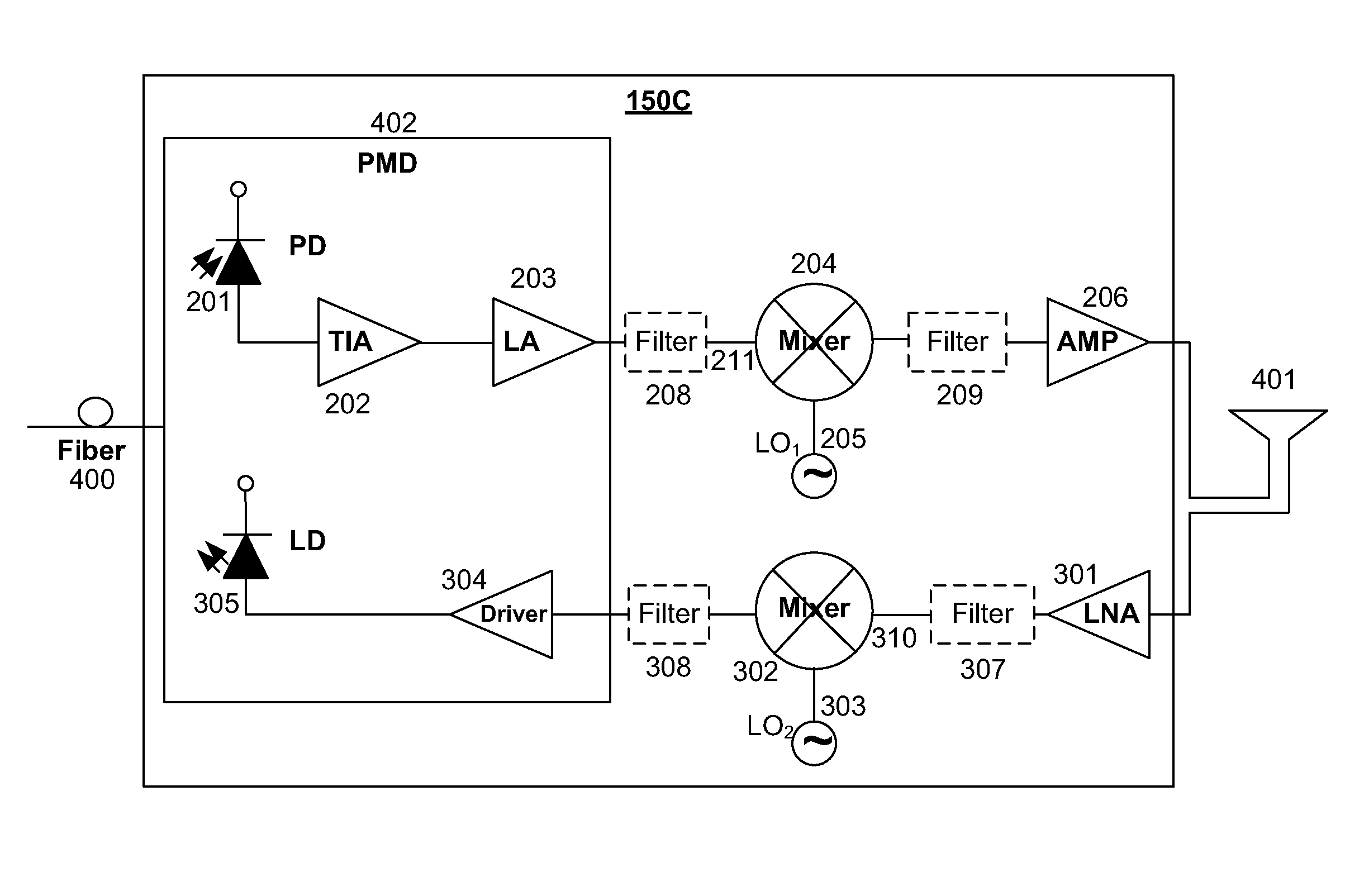
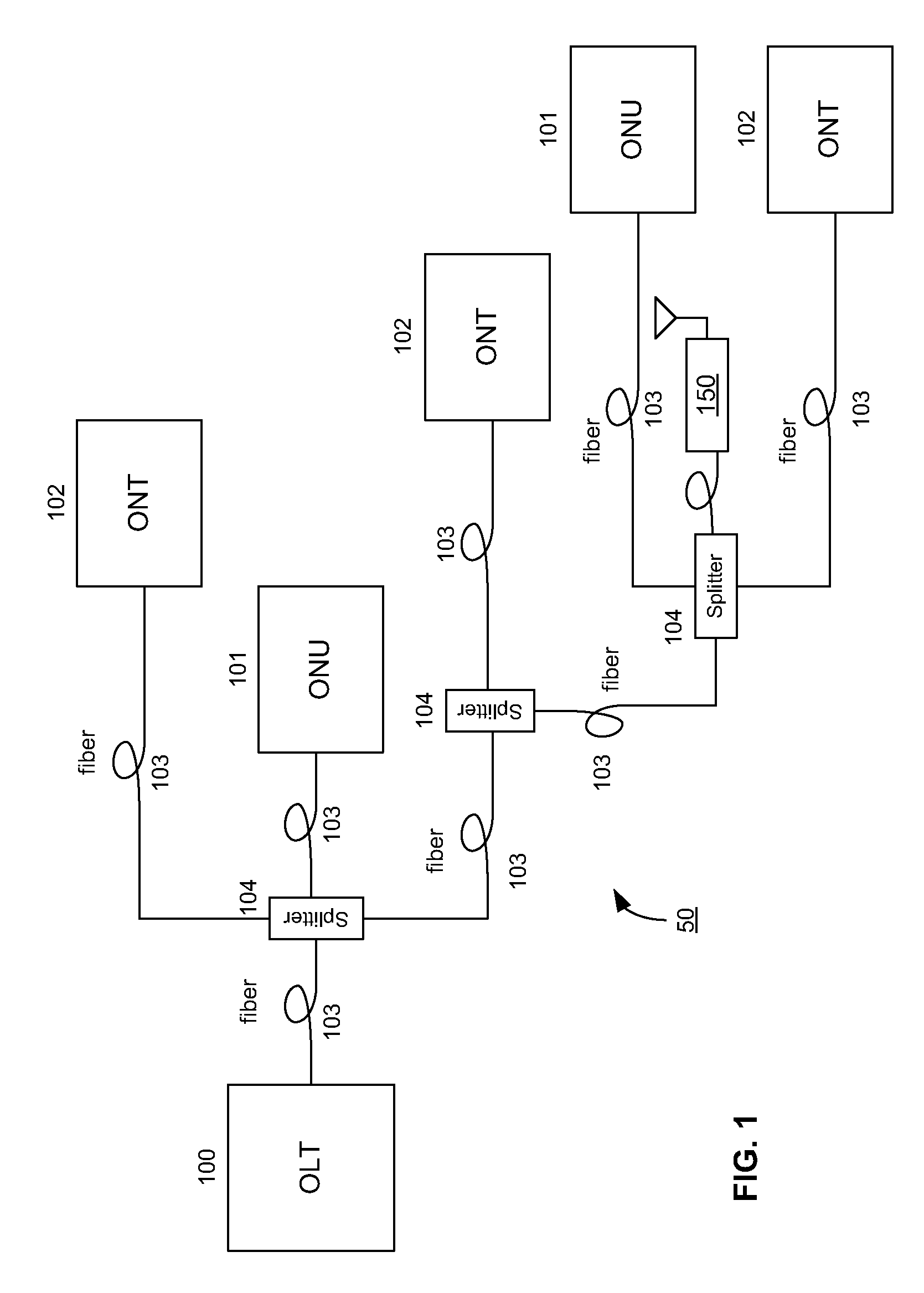
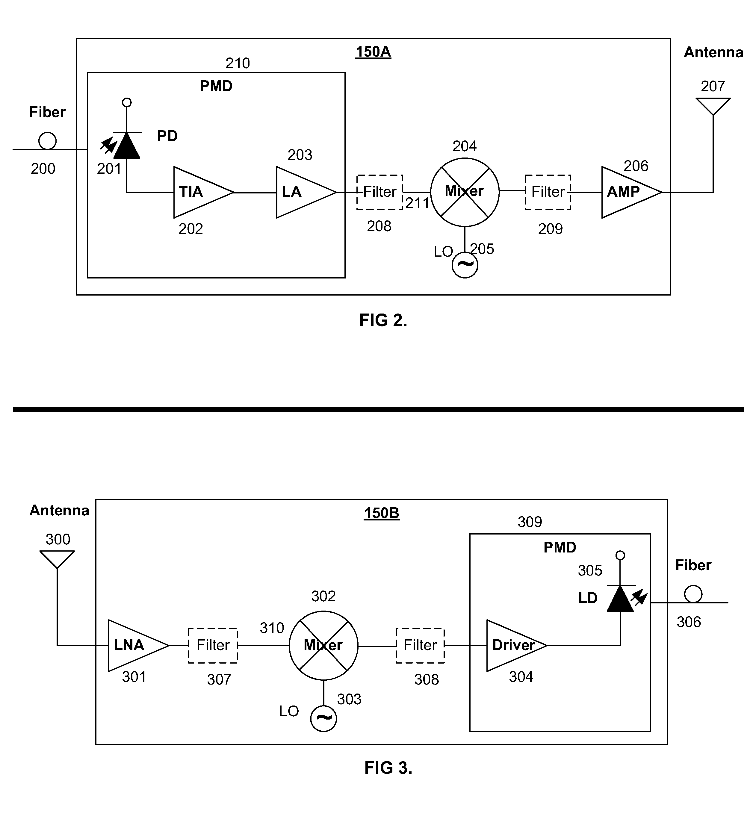
[0027]Passive Optical Network (PON) fiber links can be augmented to use radio frequency (RF) communication links. A PON can be configured in a point-to-multipoint fiber optic network in a tree-branch network architecture. FIG. 1, wherein like reference numerals designate identical or corresponding parts throughout the several views and embodiment, shows an example of a PON, where an Optical Line Terminator (OLT) 100 provides broadband communication to a plurality of client optical networking devices, including Optical Network Units (ONUs) 101 and Optical Network Terminals (ONTs) 102, at nodes in an Optical Distribution Network (ODN) 50. ODN 50 includes optical fibers 103, splitters 104, optical fiber splices (not shown) and optical fiber connectors (not shown) between an OLT 100 node and ONU 101 and ONT 102 nodes. The splitters 104 are unpowered optical splitters which generally utilize Brewster's angle principals. Any of a variety of PON embodiments may be used including embodiment...


PUM


Abstract

Passive optical networks have optical budget loss limitations that affect the ability of a Service Provider to serve a limited number of clients over a limited range. The deployment of passive optical networks is constrained by potential physical rights of way issues. A method and system for augmenting communication links of a passive optical network are disclosed which utilize radio frequency communication enabling an increase in the number of clients on the network as well as increasing the reach or range of the network while potentially eliminating physical rights of way issues.

Description

CROSS-REFERENCE TO RELATED APPLICATIONS[0001]This application is filed under 37 C.F.R. §1.53(b)(2) as a continuation-in-part claiming the benefit under 35 U.S.C. §120 of the U.S. patent application Ser. No. 10 / 867,107, “Converting Signals In Passive Optical Networks,” which was filed by the same inventors on Jun. 14, 2004 claiming the benefit under 35 U.S.C. 119(e) of U.S. Provisional Application No. 60 / 477,860 filed Jun. 12, 2003, now expired, and entirely incorporated herein by reference.FIELD OF THE INVENTION[0002]The invention relates to optical communications networks, and specifically to passive optical networks.BACKGROUND OF THE INVENTION[0003]Incumbent Local Exchange Carriers (ILECs), Competitive Local Exchange Carriers (CLECs) and other Service Providers strive to deploy the most cost effective networks possible that provide broadband service links. Cost effectiveness is a relative term often measured by comparing the cost of equipment and material (also known as Capital Ex...

Claims


Application Information

Patent Timeline
Patent Type & Authority Patents(United States)
IPC IPC(8): H04B10/00
CPCH04B10/272H04W4/18
Inventor SOTO, ALEXANDER ISOTO, WALTER G
Owner SOTO ALEXANDER I
Learn More