Method of manufacturing photonic band gap fiber base material and fiber
a technology of photonic band gap fiber and fiber, which is applied in the direction of manufacturing tools, optical fibers with polarisation, instruments, etc., can solve the problems of significant light transmission loss, and achieve the effect of suppressing transmission loss
- Summary
- Abstract
- Description
- Claims
- Application Information
AI Technical Summary
Benefits of technology
Problems solved by technology
Method used
Image

Examples
first embodiment
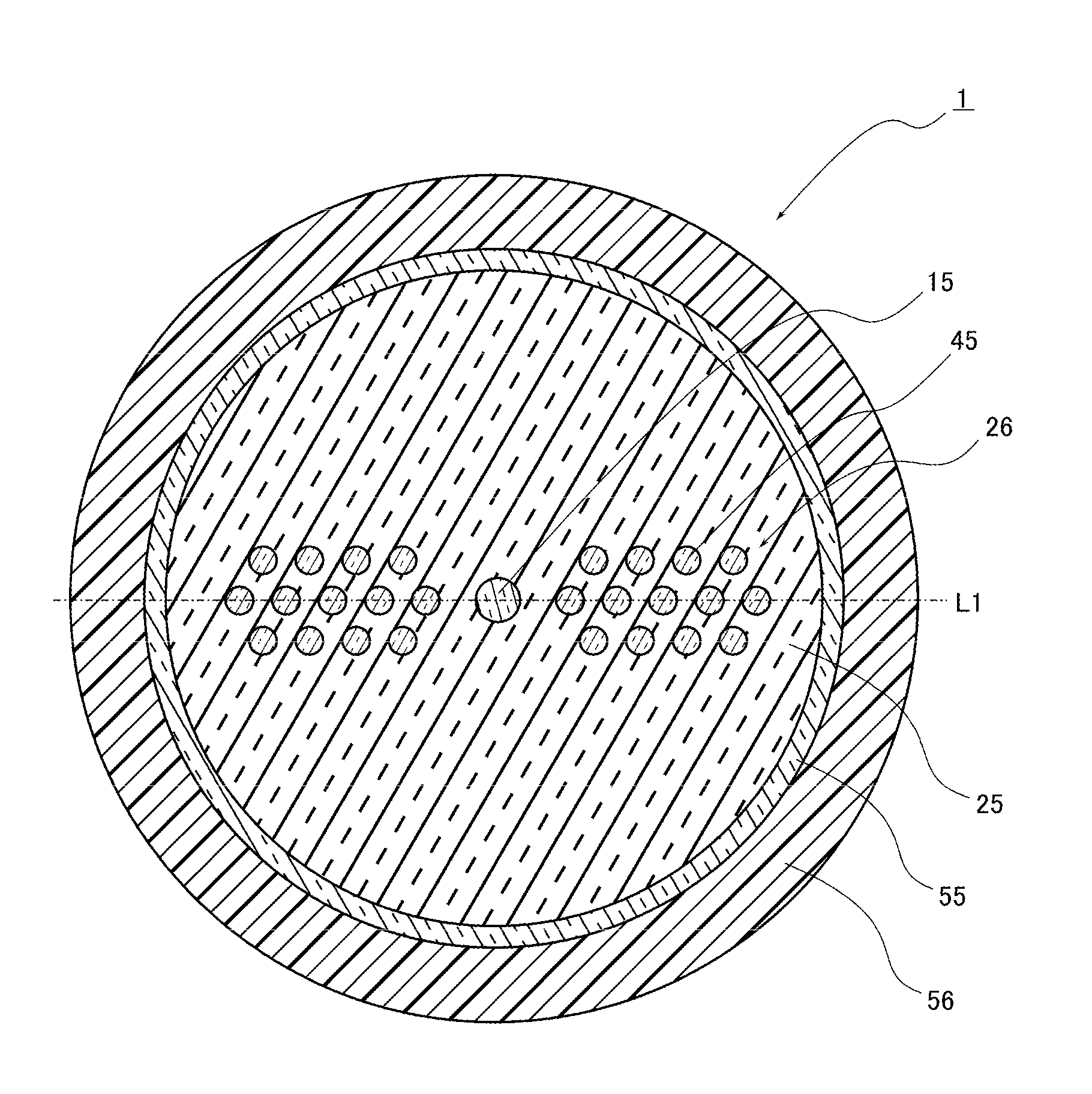
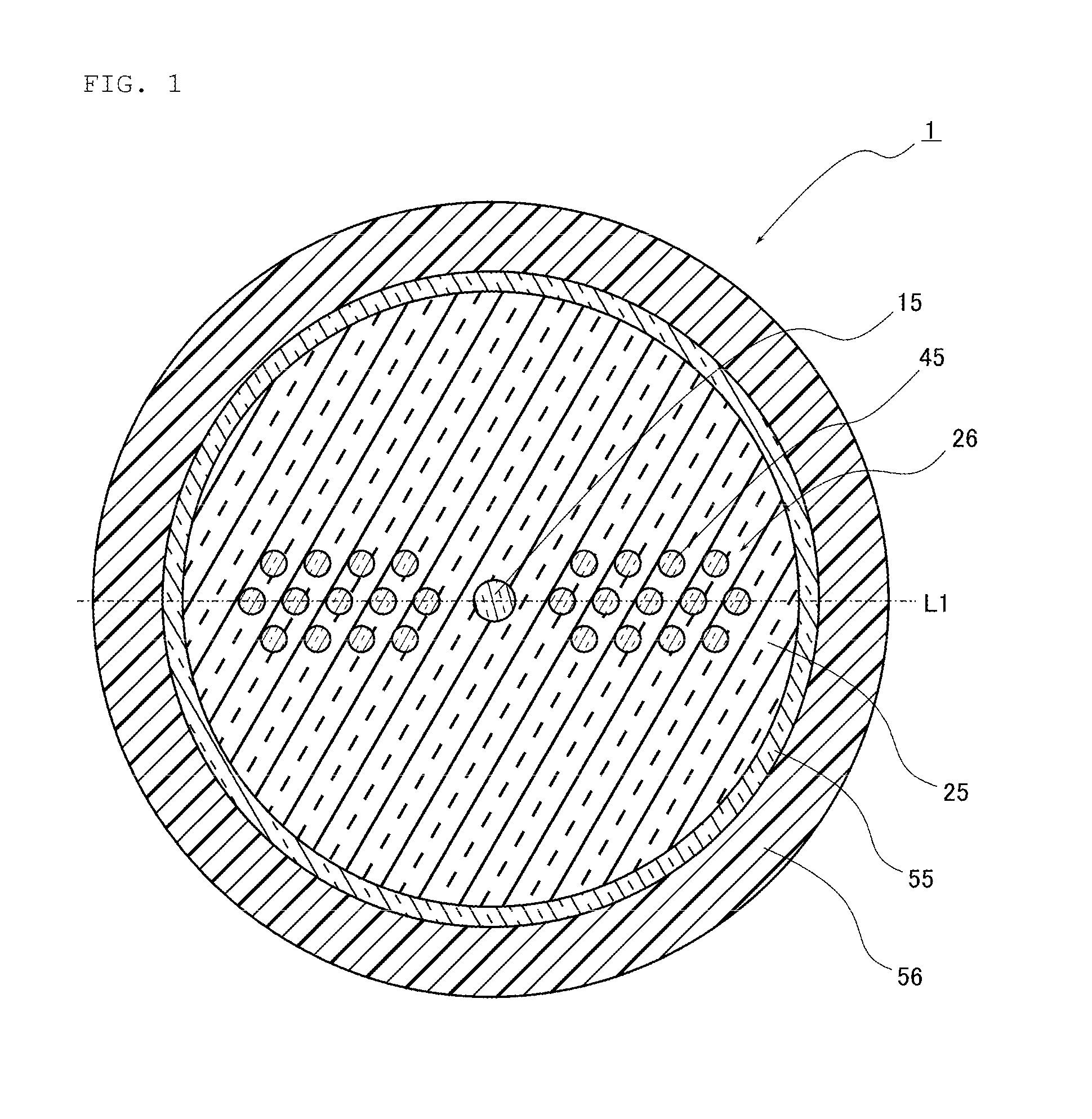
[0062]FIG. 1 is a sectional view illustrating a structure in a vertical cross section of the photonic bang gap fiber (PBGF) in a length direction according to a first embodiment of the present invention.
[0063]As illustrated in FIG. 1, a PBGF 1 has a core 15 of a circular sectional shape, periodic structure areas 26 in which a plurality of high refractive index portions 45 are formed, a clad 25 which coats the outer periphery of the core 15, a resin clad 55 which coats the outer periphery of the clad 25 and a protective layer 56 which coats the outer periphery of the resin clad 55.
[0064]A plurality of high refractive index portions 45 are aligned in one line such that, in the cross section of the PBGF 1, part of the high refractive index portions 45 overlap one line L1 extending in a radial direction passing the center of the PBGF 1. Further, the other high refractive index portions 45 are aligned in a triangular grid pattern such that the distances between adjacent high refractive i...
second embodiment
[0107]Next, a second embodiment of the present invention will be described in detail with reference to FIGS. 8 to 10. Here, components that are identical or similar to those in the first embodiment are indicated by the same reference numerals and the same explanation will not be repeated. FIG. 8 is a sectional view illustrating a structure in a vertical cross section of a PBGF in a length direction according to the present embodiment, FIG. 9 is a view illustrating the structure in the vertical cross section of an intermediate base material in the length direction after insertion step according to the present embodiment, and FIG. 10 is a sectional view illustrating the structure in the vertical cross section of a PBGF base material manufactured according to the present embodiment, in the length direction.
[0108]As illustrated in FIG. 8, a PBGF 2 according to the present embodiment differs from the PBGF 1 according to the first embodiment in that, in the vertical cross section of the P...
third embodiment
[0113]Next, a third embodiment of the present invention will be described in detail with reference to FIGS. 11 and 12. Here, components that are identical or similar to those in the first embodiment are indicated by the same reference numerals and the same explanation will not be repeated. The present embodiment is directed to another manufacturing method of manufacturing the same PBGF 1 as the first embodiment illustrated in FIG. 1. FIG. 11 is a sectional view illustrating a structure in the vertical cross section of an intermediate base material in the length direction after hole making step according to the present embodiment, and FIG. 12 is a sectional view illustrating the structure in the vertical cross section of the intermediate base material in the length direction after insertion step according to the present embodiment.
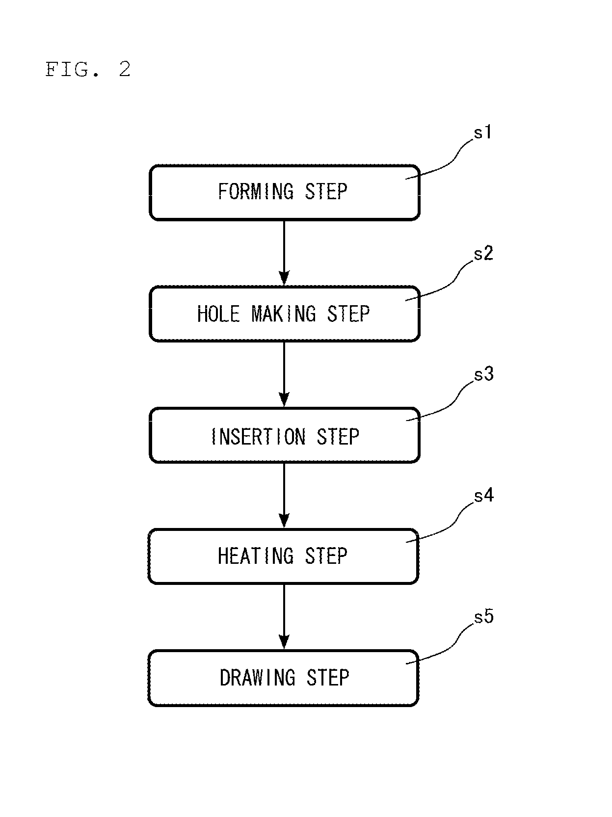
[0114]In the present embodiment, forming step s1 is performed in the same way as forming step s1 according to the first embodiment to obtain an intermediat...
PUM
| Property | Measurement | Unit |
|---|---|---|
| refractive index | aaaaa | aaaaa |
| outer diameter | aaaaa | aaaaa |
| outer diameter | aaaaa | aaaaa |
Abstract
Description
Claims
Application Information
 - R&D
- Intellectual Property
- Life Sciences
- Materials
- Tech Scout
- Unparalleled Data Quality
- Higher Quality Content
- 60% Fewer Hallucinations
Browse by: Latest US Patents, China's latest patents, Technical Efficacy Thesaurus, Application Domain, Technology Topic, Popular Technical Reports.
© 2025 PatSnap. All rights reserved.Legal|Privacy policy|Modern Slavery Act Transparency Statement|Sitemap|About US| Contact US: help@patsnap.com