Healing abutment system for bone contouring

a bone contouring and abutment technology, applied in the field of implant dentistry, can solve the problems of non-anatomical healing, difficult placement of the final crown, and maturation of the gingival tissue around a conventional circular cross-sectional (in the horizontal plane) healing collar, and achieve the effect of improving the aesthetics of conventional implant dentistry

Active Publication Date: 2013-02-26
PHILIBIN TERRY B
View PDF71 Cites 24 Cited by
  • Summary
  • Abstract
  • Description
  • Claims
  • Application Information

AI Technical Summary

Benefits of technology

[0023]It is a key object of the present invention to improve the aesthetic results of conventional implant dentistry.
[0024]It is still another object of the present invention to provide a healing abutment system that facilitates both surgical and restorative dental processes that are less uncomfortable, and less time consuming for the patent.
[0025]It is again an additional object of the present invention to provide a healing abutment system wherein prosthetic replacements for extracted teeth are accomplished more efficiently, and with improved aesthetic results, than with conventional systems.
[0028]It is a further object of the present invention to provide a healing abutment system for bone contouring, containment, and stabilization, which is more effective in contouring, containment, and stabilization of alveolar bone graft materials.
[0029]It is a further object of the present invention to provide a healing abutment system for bone contouring, containment, and stabilization in which the process and technique of placing healing abutments are made more effective in contouring, containment, and stabilization of alveolar bone graft materials.
[0030]It is an additional object of the present invention to provide a healing abutment system for bone contouring, containment, and stabilization in which the healing abutments are made more effective in contouring surrounding gingiva.

Problems solved by technology

The afore-mentioned anti-rotation locking devices would be unnecessary for conventional healing abutments due to the circular shape of the healing abutment and the need to easily slide them past partially healed gingiva to quickly and easily fit into an existing dental implant.
A disadvantage to the single stage surgical procedure is that maturation of the gingival tissue around a conventional circular cross-sectional (in the horizontal plane) healing collar, heals in a non-anatomic shape.
This situation can make the placement of the final crown more difficult.
As the gingival tissue matures in a non-anatomic shape it is less resilient to the outward pressure of the final crown's (prosthetic tooth) greater overall dimension and different shape, which can cause a mismatch between gingiva and crown.
This can hinder the complete seating (cementation) of the final crown.
This situation can cause the crown to be incompletely connected onto the abutment, therefore requiring reduction of the crown's occlusal surface or resulting in open regions between the abutment and crown interface.
Open regions between the abutment and crown can cause cement extrusion into the surgical site resulting in an inflammatory tissue response and compromised healing.
Both stability and aesthetics can be compromised.
A disadvantage of immediate dental implant placement after tooth extraction is the possibility of initial reduced stability of the implant fixture due to the implant osteotomy not having the same shape as the tooth root socket.
With lack of gingival tissue to help retain the bone graft, the graft can become unstable.
A conventional circular healing abutment does not allow for complete occlusion of the gingival opening and stabilization of the bone graft.
However, their lack of rigidity can also lead to bone graft instability.
This lack of bone graft stability can lead to loss of the bone graft and non-ideal alveolar bone anatomy.
Non-ideal alveolar bone anatomy around a dental implant will ultimately lead to displeasing aesthetic results.
Such systems have only occasionally been successful in contouring gingiva, and providing acceptable final aesthetic results.
Custom made temporary prostheses have also been used but are labor intensive, take multiple appointments, and do not contour, contain, and stabilize bone graft materials.
This approach can be very time consuming, expensive for the patient, and only addresses the gingival tissue.
If the distance between the landmarks is greater than the recommended guidelines then the probability for incomplete presence of the interdental papilla increases and esthetics becomes less favorable.
However, conventional techniques have proven unreliable in controlling the desired contouring of gingiva.

Method used


Image

  • Healing abutment system for bone contouring
  • Healing abutment system for bone contouring
  • Healing abutment system for bone contouring

Examples


Embodiment Construction

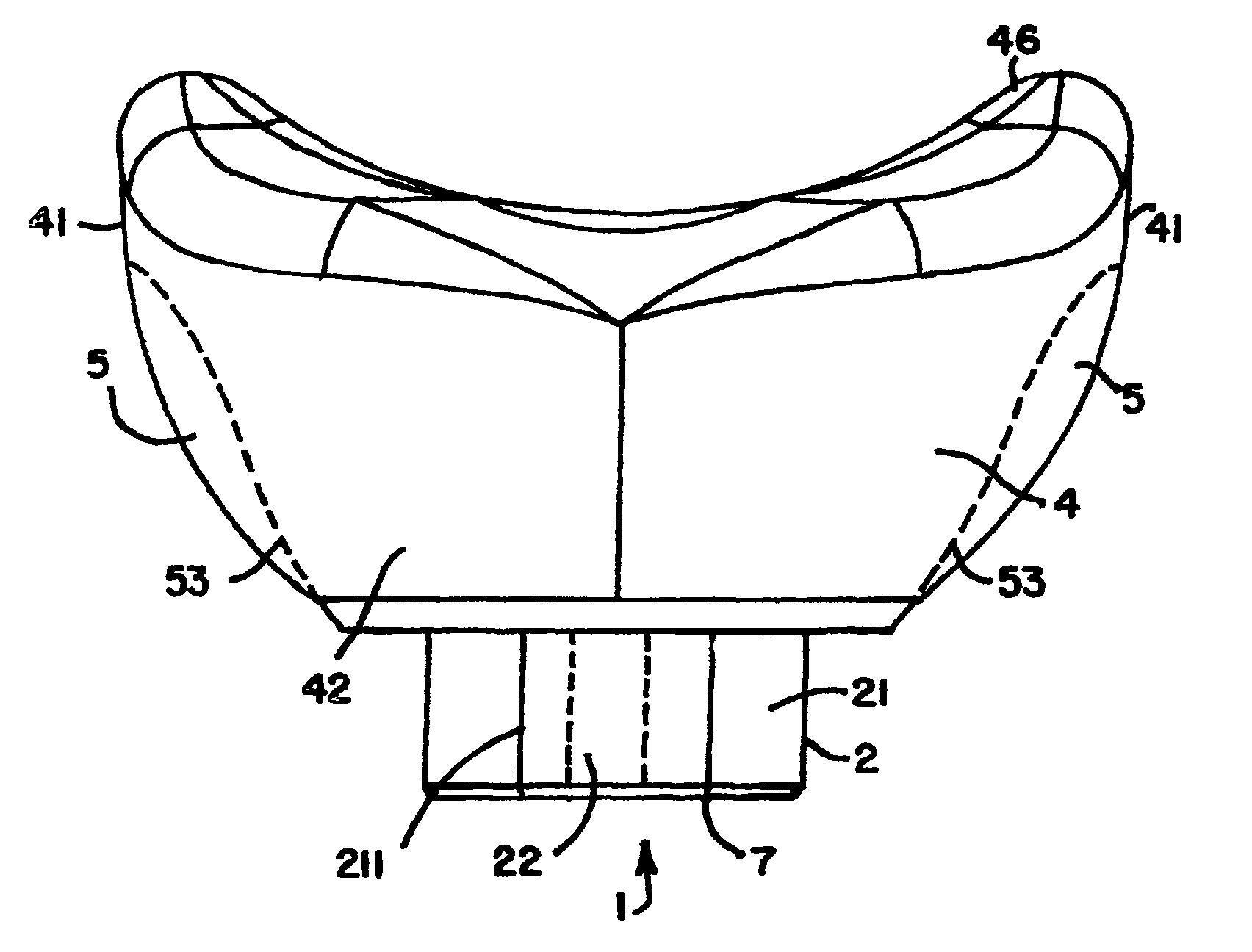
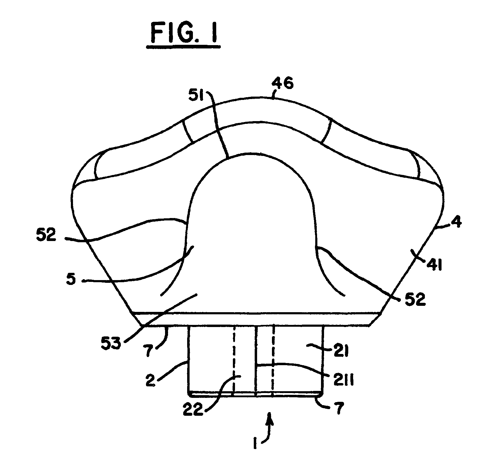
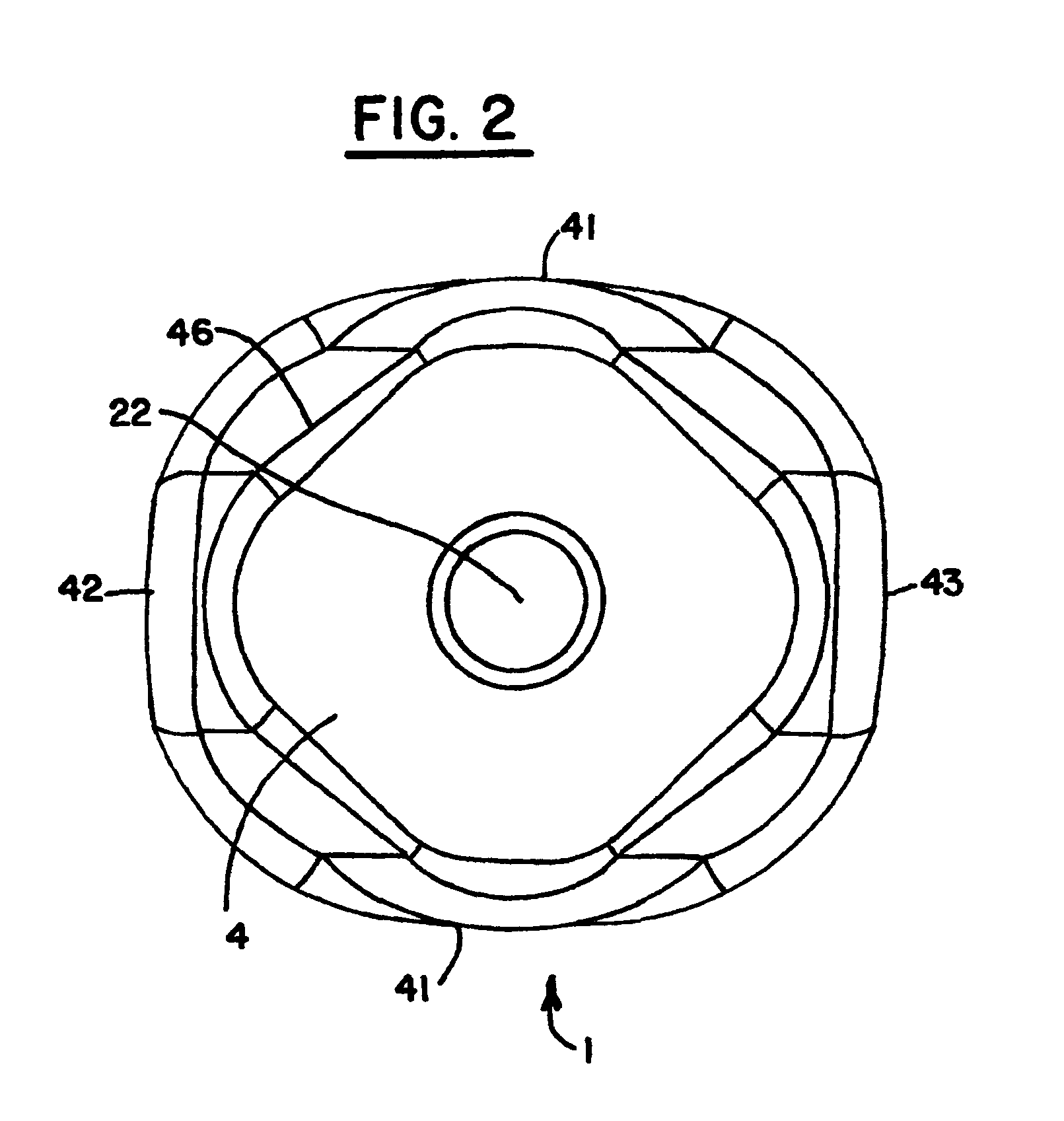
[0040]The present invention is directed to a system for contouring bone growth at missing tooth or tooth extraction sites 100 (in FIG. 6). The environment hardware used is constituted by standard dental implants 10 as currently used in advanced implant dentistry. In the inventive system, at least a partially anatomic bone graft contouring abutment 1, as depicted in FIGS. 1-5, is attached to a standard implant 10, as depicted in FIGS. 6 and 7.

[0041]In the inventive system, the bone graft contouring abutment 1 is substituted for a conventional healing abutment. Bone graft material 30 is built up around bone graft contouring abutment 1 to help hold implant 10. Unlike conventional healing abutments, the bone graft contouring abutment of the present invention mimics at least partially, the anatomical characteristics of the extracted tooth / toothroot, at least in the horizontal plane. Accordingly, the size and shape of the bone graft contouring abutment 1 changes in accordance with the too...


PUM


Abstract

The present invention uses an anatomically shaped bone graft contouring abutment in place of a conventional healing abutment to control the bone graft for optimal height. The extraction site aesthetics, in the form of enhanced gingival growth, are facilitated by the optimal bone graft placement.

Description

PRIORITY INFORMATION[0001]The present invention claims priority to U.S. Provisional Application No. 61 / 476,360 filed on Apr. 18, 2011, making reference herein to same in its entirety.FIELD OF THE INVENTION[0002]The present invention relates in general to implant dentistry. In particular, the present invention is directed to the maximization of interseptal alveolar bone height around a dental implant's most superior surface thereby optimizing final dental implant aesthetic results.BACKGROUND ART[0003]The success of implant dentistry was vastly improved by the incorporation of osseointegration. Osseointegration was originally discovered by Dr. P. Bränemark in the 1950s and 1960's using titanium implants. Dr. Branemark, an orthopedic surgeon, discovered that when titanium was implanted into bone, the two substances fused safely and securely. This appeared to provide a permanent solution to the old problem of replacing missing teeth with a durable, stable substitute for the original too...

Claims


Application Information

Patent Timeline
Patent Type & Authority Patents(United States)
IPC IPC(8): A61C8/00
CPCA61C8/008A61C8/0006
Inventor PHILIBIN, TERRY B.
Owner PHILIBIN TERRY B
Why Eureka
Try Eureka