
Ambient-air pulsed valve for internal combustion engines equipped with a turbocharger

a technology of internal combustion engine and air control valve, which is applied in the direction of valve details, valve operating means/releasing devices, mechanical apparatus, etc., can solve the problems of thermodynamic problems, turbo-speed reduction, etc., and achieve simple and inexpensive sealing, simple manufacturing, and simple effect of realization

Inactive Publication Date: 2013-03-05
PIERBURG GMBH & CO KG NEUSS
View PDF35 Cites 10 Cited by
  • Summary
  • Abstract
  • Description
  • Claims
  • Application Information

AI Technical Summary

Benefits of technology

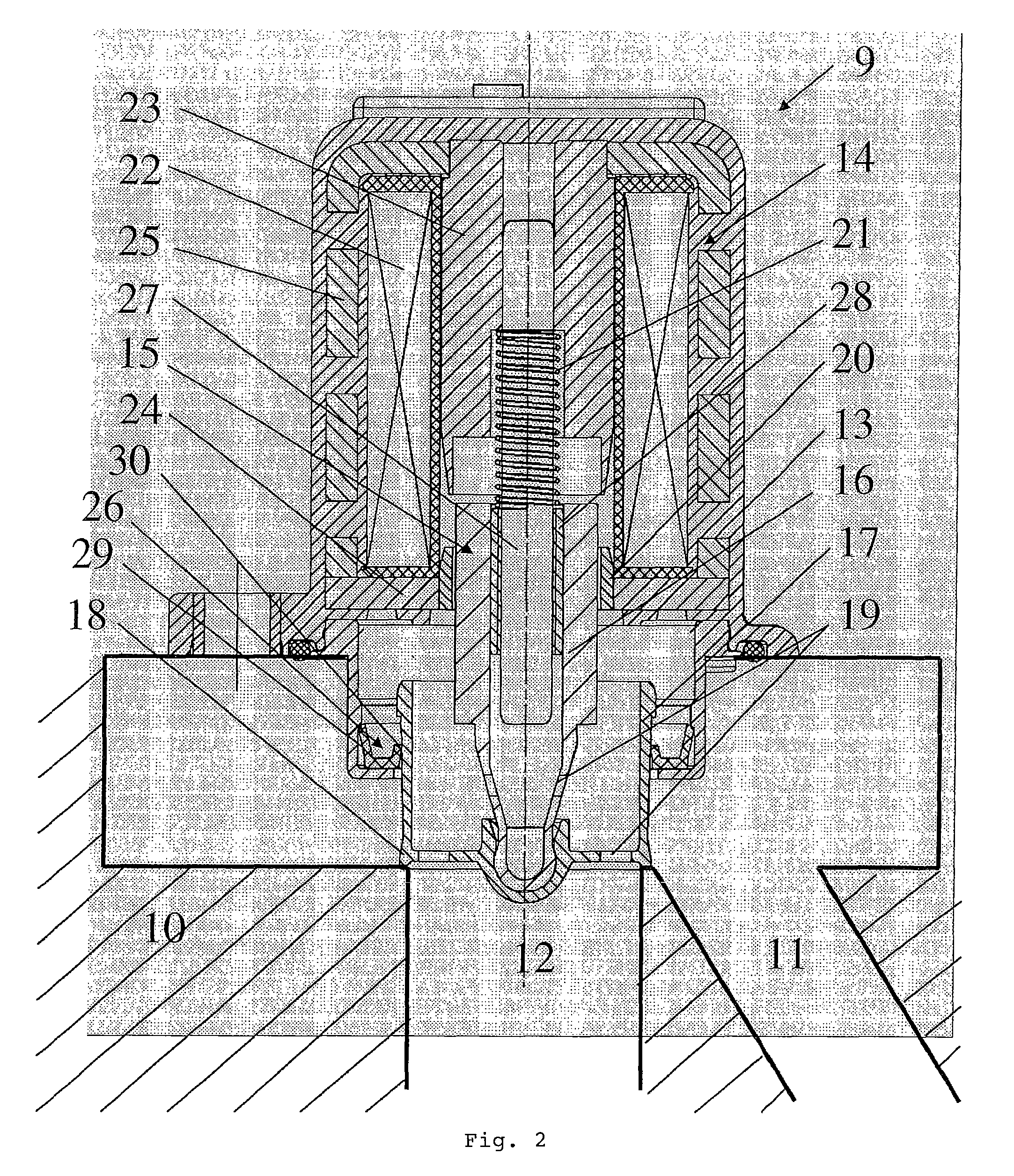
This present invention is an air control valve for internal combustion engines with a turbocharger. The valve is placed between the pressure and intake sides of the boost pressure pump, and has a housing with an electromagnetic drive unit and a movable valve unit. The valve closing body is cylindrical and has a sealing element that ensures a tight seal with the housing. The valve closing body also has a conical shape, which reduces friction between the sealing ring and the closing body, resulting in less energy consumption. The valve closing body also has pressure compensation openings that are spaced from the sealing element, ensuring a balance of pressure during the opening and closing phases. The technical effects of this invention include its ability to be connected with both the pressure and intake sides of the boost pressure pump, as well as its simplified and cost-effective manufacturing process.

Problems solved by technology

The connection between the pressure side and the intake side of a boost pressure pump of a turbocharger via a bypass line is required for a transition from high load to overrun conditions of the internal combustion engine in order to prevent a high delivery rate of the boost pressure pump against a closed throttle flap, and the resultant pumping effects as well as a sudden excessive decrease in the turbo-speed resulting in thermodynamics problems.

Method used


Image

  • Ambient-air pulsed valve for internal combustion engines equipped with a turbocharger
  • Ambient-air pulsed valve for internal combustion engines equipped with a turbocharger
  • Ambient-air pulsed valve for internal combustion engines equipped with a turbocharger

Examples


Embodiment Construction

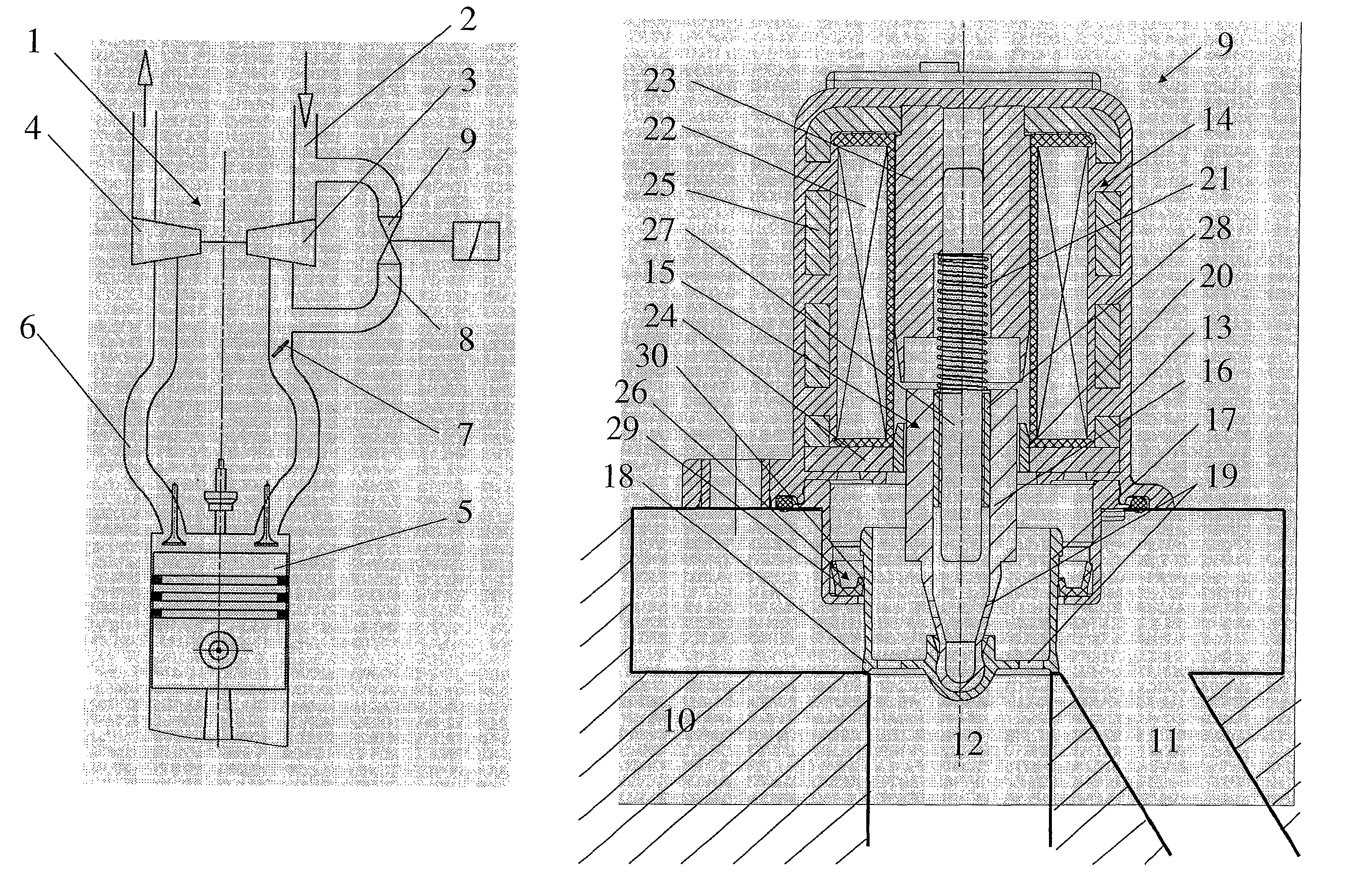
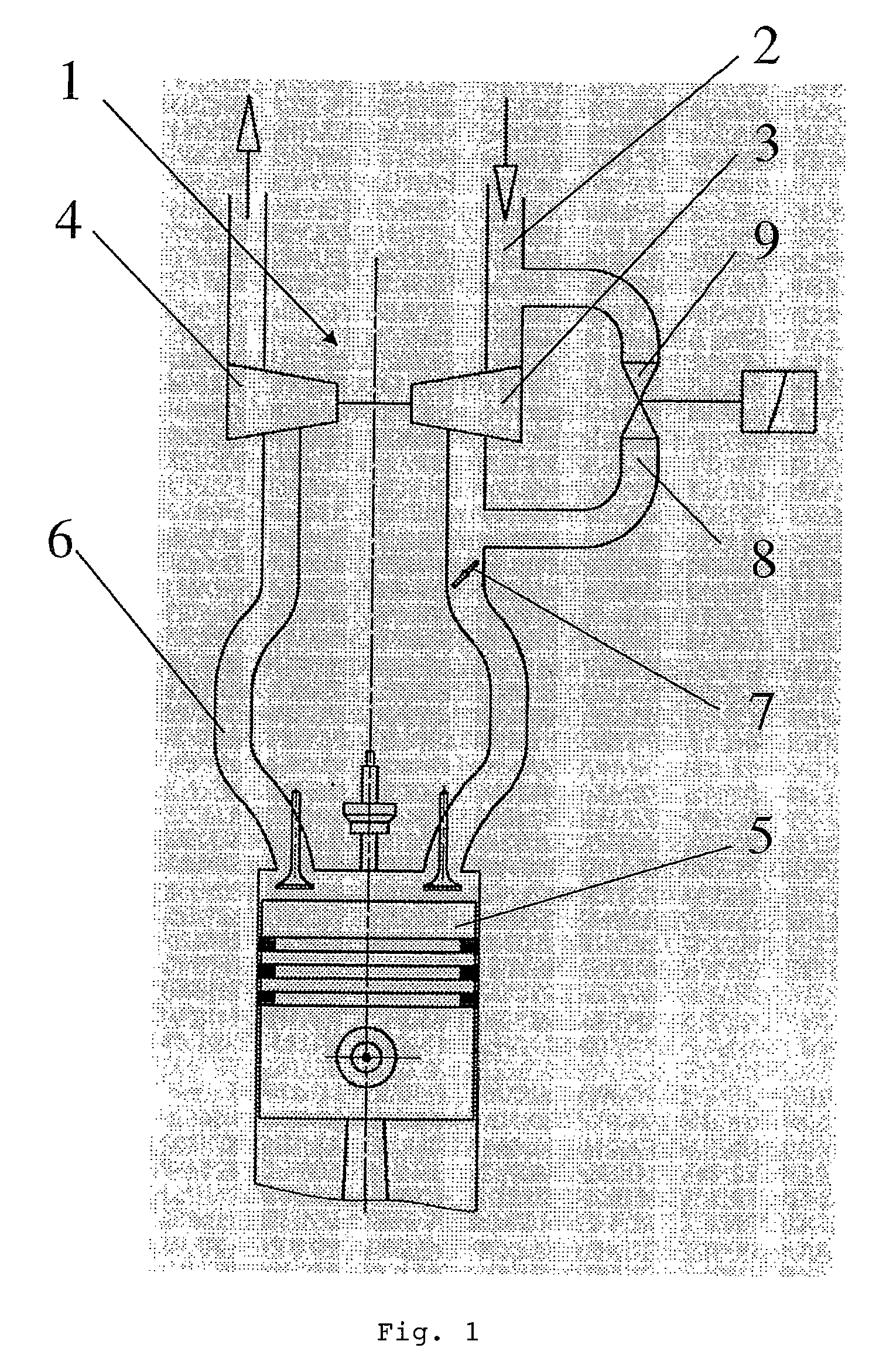
[0017]FIG. 1 shows a schematic representation of an internal combustion engine, which is not illustrated in detail, comprising a turbocharger 1. Via an intake line 2 ambient air is taken in and compressed by the compressor 3 which is driven by an exhaust-side turbine 4, and subsequently fed to the combustion chamber 5 of the internal combustion engine. Via the exhaust line 6 and the turbine 4 the exhaust gas is then discharged from the combustion chamber 5. The control of the intake air to be fed to the combustion chamber 5 is realized by a throttle flap 7. When a quick-closing throttle flap is used, the quick closing action being provoked by a sudden deceleration, for example, a pumping effect of the turbocharger, which continues to rotate, against the closed throttle flap 7 is prevented in a known manner by providing a bypass line 8 comprising an air control valve 9. Via this bypass line 8 compressed intake air can be returned to the region of the intake line 2 upstream of the com...


PUM


Abstract

An air control valve for internal combustion engines having a turbocharger, is placed inside a bypass channel between a pressure side and an intake side of a boost pressure pump of the turbocharger, and has a housing which incorporates an electromagnetic drive unit and a valve unit movable in the housing. The valve unit has a valve rod and a valve closing body attached thereto and a circular sealing element. An arrangement is provided to keep the moving valve unit in a closed position when no current is supplied to the valve unit. At least one pressure compensation opening is provided in the moving valve unit, and the valve closing body has a cylindrical lateral surface which is arranged in such a manner that a housing interior is sealed towards the pressure side or the intake side.

Description

[0001]This is a National Phase Application in the United States of International Patent Application No. PCT / EP2006 / 067833 filed Oct. 26, 2006, which claims priority on German Patent Application No. DE 10 2005 051 971.7, filed Oct. 25, 2005. The entire disclosures of the above patent applications are hereby incorporated by reference.FIELD OF THE INVENTION[0002]The invention relates to an air control valve for internal combustion engines comprising a turbocharger wherein the air control valve includes a valve closing body that comprises a cylindrical lateral surface cooperating with means such that a housing interior is sealed towards the pressure side or the intake side.BACKGROUND OF THE INVENTION[0003]Such air valves control are well known and are in particular described in DE 100 20 041 C2. The connection between the pressure side and the intake side of a boost pressure pump of a turbocharger via a bypass line is required for a transition from high load to overrun conditions of the...

Claims


Application Information

Patent Timeline
Patent Type & Authority Patents(United States)
IPC IPC(8): F02B33/44F16K31/02F16K39/00
CPCF02B37/16F16K31/0693F16K31/0655Y02T10/144F16K39/022Y02T10/12
Inventor THIERY, MICHAELHERRMANN, MAXKRAUSE, HARALDDISMON, HEINRICHNOWAK, MARTINLAPPAN, ROLF
Owner PIERBURG GMBH & CO KG NEUSS
Learn More