Method for thinning a sample and sample carrier for performing said method

a sample and carrier technology, applied in the field of thinning a sample, can solve the problems of time-consuming and laborious welding of the probe to the sample, and the inability to thin the sample, so as to improve the parallelism, improve the accuracy of thinning, and improve the alignment of the sample

Active Publication Date: 2013-03-05
FEI CO
View PDF19 Cites 3 Cited by
  • Summary
  • Abstract
  • Description
  • Claims
  • Application Information

AI Technical Summary

Benefits of technology

[0016]The invention describes a sample carrier for thinning a sample taken from e.g. a semiconductor wafer. In one embodiment, the sample carrier comprises a rigid structure of, for example, copper with an outer boundary and a supporting film, e.g., made of carbon, extending beyond the outer boundary. By placing the sample on the supporting film, the sample can be attached to the rigid structure using Electron Beam Induced Deposition (EBID), Ion Beam Induced Deposition (IBID), Laser Beam Induced Deposition (LBID), or by placing a small droplet of glue or resin between the sample and the rigid structure. The supporting film aligns the samples when they are placed onto it. After attaching the sample to the rigid structure the sample can be thinned with an ion beam, during which thinning the supporting film is locally removed as well. The invention results in better alignment of the sample to the sample carrier, and also in more freedom how the sample is transported from the wafer to the sample carrier, e.g. with the help of an electrically charged glass needle. The latter eliminates the attaching / severing steps that are normally associated with the transport of a sample to a sample carrier.

Problems solved by technology

Incorrect alignment may result in warping of the sample during milling, but may e.g. also result in problems during the subsequent inspection / analysis.
A disadvantage of the known method is that welding the probe to the sample and severing the sample from the probe takes time.
However, it is then not possible to thin the sample after extraction of the sample from the wafer.
Ex-situ lift-out also makes it more difficult to do so-named end-pointing.
Using the ex-situ method, both sides of the sample are formed between the two surfaces of the wafer, and are thus not freely accessible.
Another disadvantage of the known method is that, after attaching the sample to the sample carrier, the orientation of e.g. the crystallographic axes in the sample with respect to the sample carrier is insufficiently reproducible.
This hinders automation of the thinning process.

Method used


Image

  • Method for thinning a sample and sample carrier for performing said method
  • Method for thinning a sample and sample carrier for performing said method
  • Method for thinning a sample and sample carrier for performing said method

Examples


Embodiment Construction

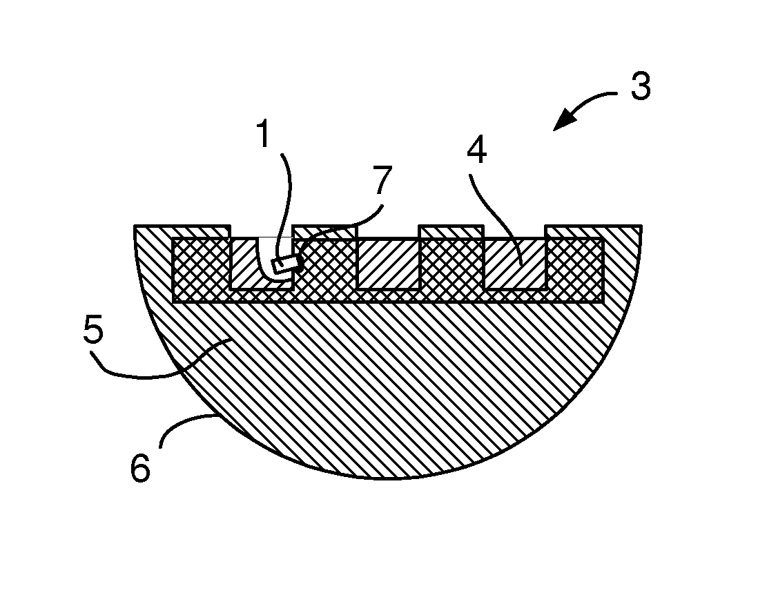
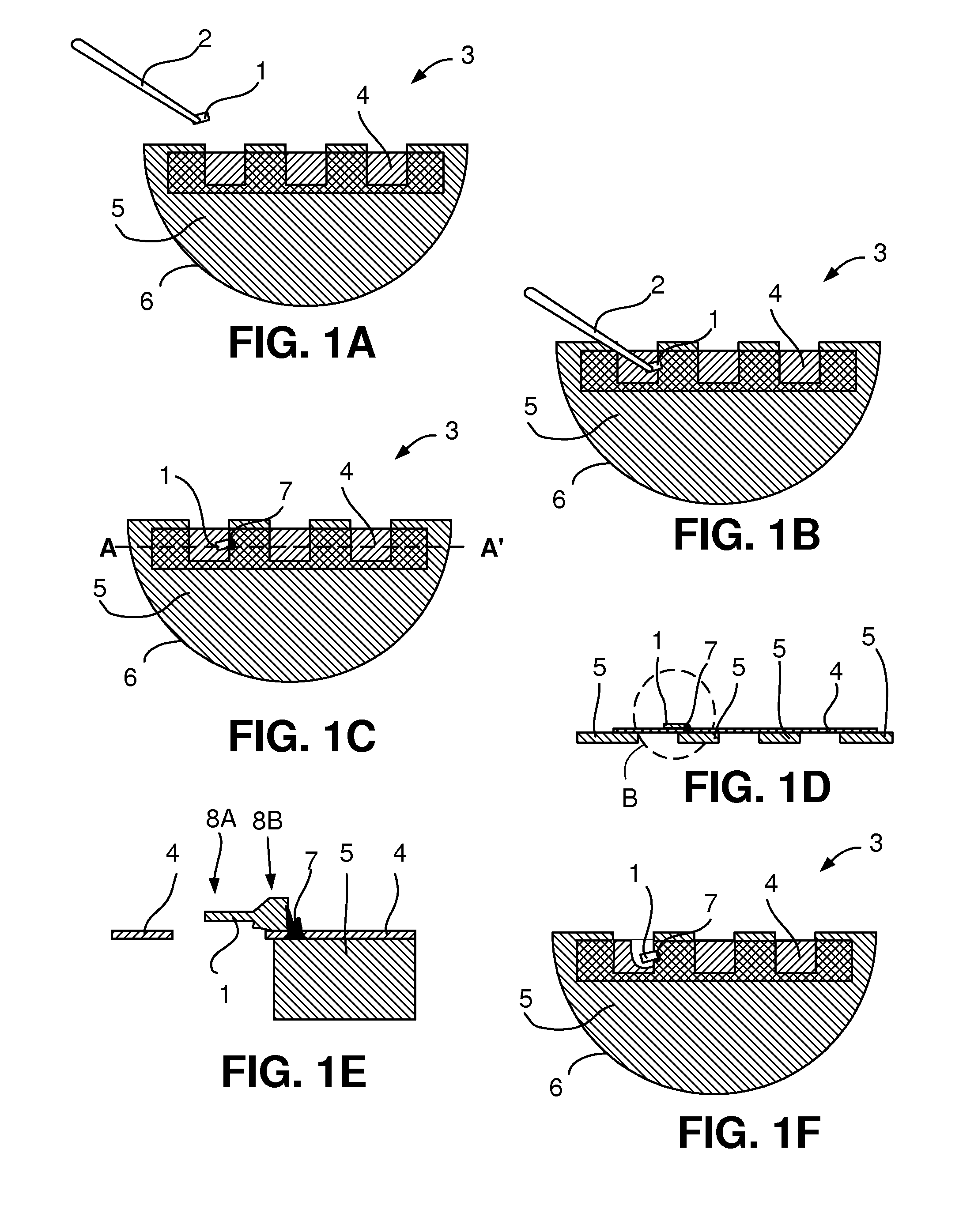
[0025]To that end the method according to the invention is characterized in that[0026]the sample carrier is provided with a supporting film adhered to said rigid structure, said supporting film at least partially extending beyond the boundary to which the sample can be attached, and[0027]before attaching the sample to the rigid structure the sample is placed on the supporting film.

[0028]The sample carrier used in the method according to the invention comprises a rigid structure to which the sample is attached, and a supporting film on which the sample is placed before attaching the sample to the rigid structure of the sample carrier. By placing the sample on the supporting film, the sample can then be attached to the rigid structure with e.g. Electron Beam Induced Deposition (EBID), Ion Beam Induced Deposition (IBID), Laser Beam Induced Deposition (LBID), or e.g. by placing a small droplet of glue or resin between the sample and the rigid structure.

[0029]It is remarked that the samp...


PUM

PropertyMeasurementUnit
TEMaaaaaaaaaa
areaaaaaaaaaaa
Microscopyaaaaaaaaaa

Abstract

A sample carrier (3) for thinning a sample (1) taken from e.g. a semiconductor wafer. The sample carrier comprises a rigid part (5), e.g. made of e.g. copper, with an outer boundary (6), and a supporting film (4), e.g. made of carbon, extending beyond the outer boundary. By placing the sample on the supporting film, the sample can be attached to the rigid structure using e.g. IBID. The supporting film aligns the samples when they are placed onto it. After attaching the sample to the rigid structure the sample can be thinned with e.g. an ion beam, during which thinning the supporting film is locally removed as well. The invention results in better alignment of the sample to the sample carrier, and also in more freedom how the sample is transported from the wafer to the sample carrier, e.g. with the help of an electrically charged glass needle (2). The latter eliminates the attaching / severing steps that are normally associated with the transport of a sample to a sample carrier.

Description

BACKGROUND AND SUMMARY OF THE INVENTION[0001]The invention relates to a method for thinning a sample, the method comprising:[0002]providing a sample attached to a probe,[0003]providing a sample carrier, said sample carrier showing a rigid structure, said rigid structure showing an boundary to which the sample can be attached,[0004]attaching the sample to the boundary of the rigid structure, and[0005]exposing the sample to a milling process or an etching process so as to at least partially thin the sample.[0006]The invention further relates to a sample carrier equipped to perform the method according to the invention.[0007]Such a method is known from “The total release method for FIB in-situ TEM sample preparation”, T. M. Moore, Microscopy Today, Vol. 13, No. 4, pages 40-42, more specifically page 40, column 2 as “The total release method for in-situ lift-out”.[0008]Such a method is used in e.g. the semiconductor industry, where samples are taken from semiconductors for inspection / an...

Claims


Application Information

Patent Timeline
Patent Type & Authority Patents(United States)
IPC IPC(8): G01F23/00G21K5/08G21K5/10
CPCH01J37/20H01J37/3056H01J2237/31745
Inventor LEHMANN, RALF
Owner FEI CO
Why Eureka
Try Eureka