High speed acquisition vision system and method for selectively viewing object features

a high-speed acquisition and feature technology, applied in the field of optical imaging systems and methods, can solve the problems of serious technical challenges, inability to scan, and inability to selectively view object features, and achieve the effect of substantially reducing the aperture of the illuminating light sour

Active Publication Date: 2013-03-05
ORBOTECH LTD
View PDF14 Cites 7 Cited by
  • Summary
  • Abstract
  • Description
  • Claims
  • Application Information

AI Technical Summary

Benefits of technology

[0007]In accordance with one aspect of the described methodology, there is provided an optical apparatus for creating an image of an object having non-transparent material. The described apparatus includes an illuminating light source producing an illuminating light having a controlled angular spectrum; an infinity corrected objective directing the illuminating light on the object and collecting light from the object; an illumination optical path delivering the illuminating light from the illuminating light source to the infinity-corrected objective; a relay optics disposed within the illumination optical path for introducing a predetermined tilt angle for rays of the illuminating light entering the infinity corrected objective; an image sensor for creating the image of the object; and an imaging optical path for delivering the collected light from the infinity-corrected objective to the image sensor. In the described optical apparatus, the illuminating light source, the infinity corrected objective and the relay optics are arranged to at least partially prevent stray light rays, rays, scattered by the surface or interface of the non-transparent material and light rays, perturbed by inhomogeneities of the non-transparent material, from entering the imaging optical path.
[0009]In accordance with yet another aspect of the described methodology, there is provided an optical apparatus for creating an image of an object including an object feature. The described apparatus includes an illuminating light source having an emitting aperture and producing an illuminating light having a controlled angular spectrum; an infinity corrected objective directing the illuminating light on the object and collecting light from the object; an illumination optical path delivering the illuminating light from the illuminating light source to the infinity-corrected objective; a relay optics disposed within the illumination optical path for introducing a predetermined tilt angle for rays of the illuminating light entering the infinity corrected objective; an image sensor for creating the image of the object; and an imaging optical path for delivering the collected light from the infinity-corrected objective to the image sensor. In the described apparatus, the emitting aperture of the illuminating light source is substantially reduced and the relay optics is configured to provide a strongly divergent or a strongly convergent illuminating light incident on the object.
[0010]In accordance with a further aspect of the described methodology, there is provided a method for creating an image of an object including non-transparent material. The inventive method involves producing, using an illuminating light source, an illuminating light having a controlled angular spectrum; directing, using an infinity corrected objective, the illuminating light on the object and collecting light from the object; delivering, using an illumination optical path, the illuminating light from the illuminating light source to the infinity-corrected objective; introducing, using a relay optics disposed within the illumination optical path, a predetermined tilt angle for rays of the illuminating light entering the infinity corrected objective; creating, using an image sensor, the image of the object; and delivering, using an imaging optical path, the collected light from the infinity-corrected objective to the image sensor. In the inventive method, the illuminating light source, the infinity corrected objective and the relay optics are used to at least partially prevent stray light rays, rays, scattered by the surface or interface of the non-transparent material and light rays, perturbed by inhomogeneities of the non-transparent material, from entering the imaging optical path.
[0012]In accordance with yet further aspect of the described methodology, there is provided a method for creating an image of an object including an object feature. The inventive method involves producing, using an illuminating light source having an emitting aperture, an illuminating light having a controlled angular spectrum; directing, using an infinity corrected objective, the illuminating light on the object and collecting light from the object; delivering, using an illumination optical path, the illuminating light from the illuminating light source to the infinity-corrected objective; introducing, using a relay optics disposed within the illumination optical path, a predetermined tilt angle for rays of the illuminating light entering the infinity corrected objective; creating, using an image sensor, the image of the object; and delivering, using an imaging optical path, the collected light from the infinity-corrected objective to the image sensor. In the inventive method, the emitting aperture of the illuminating light source is substantially reduced and the relay optics is configured to provide a strongly divergent or a strongly convergent illuminating light incident on the object.

Problems solved by technology

Viewing of object features buried under “nontransparent materials” represents a serious technical challenge, especially when the optical vision system must be capable of generating real time live images of the object and the object features do not transmit light.
Scanning is not an acceptable solution in such vision systems and back light illumination cannot be used because the object features themselves do not transmit backlight.
As would be appreciated by persons of skill in the art, using ultraviolet or infrared sources of light for illumination of the nontransparent object together with imaging sensors having sensitivity in the corresponding wavelength ranges considerably increases the overall cost of the optical inspection system and, therefore, is undesirable.
In addition, the use of infrared illumination light sources is disfavored because the optical resolution of the imaging system decreases with the increase of the wavelength of the illuminating light.

Method used


Image

  • High speed acquisition vision system and method for selectively viewing object features
  • High speed acquisition vision system and method for selectively viewing object features
  • High speed acquisition vision system and method for selectively viewing object features

Examples


Embodiment Construction

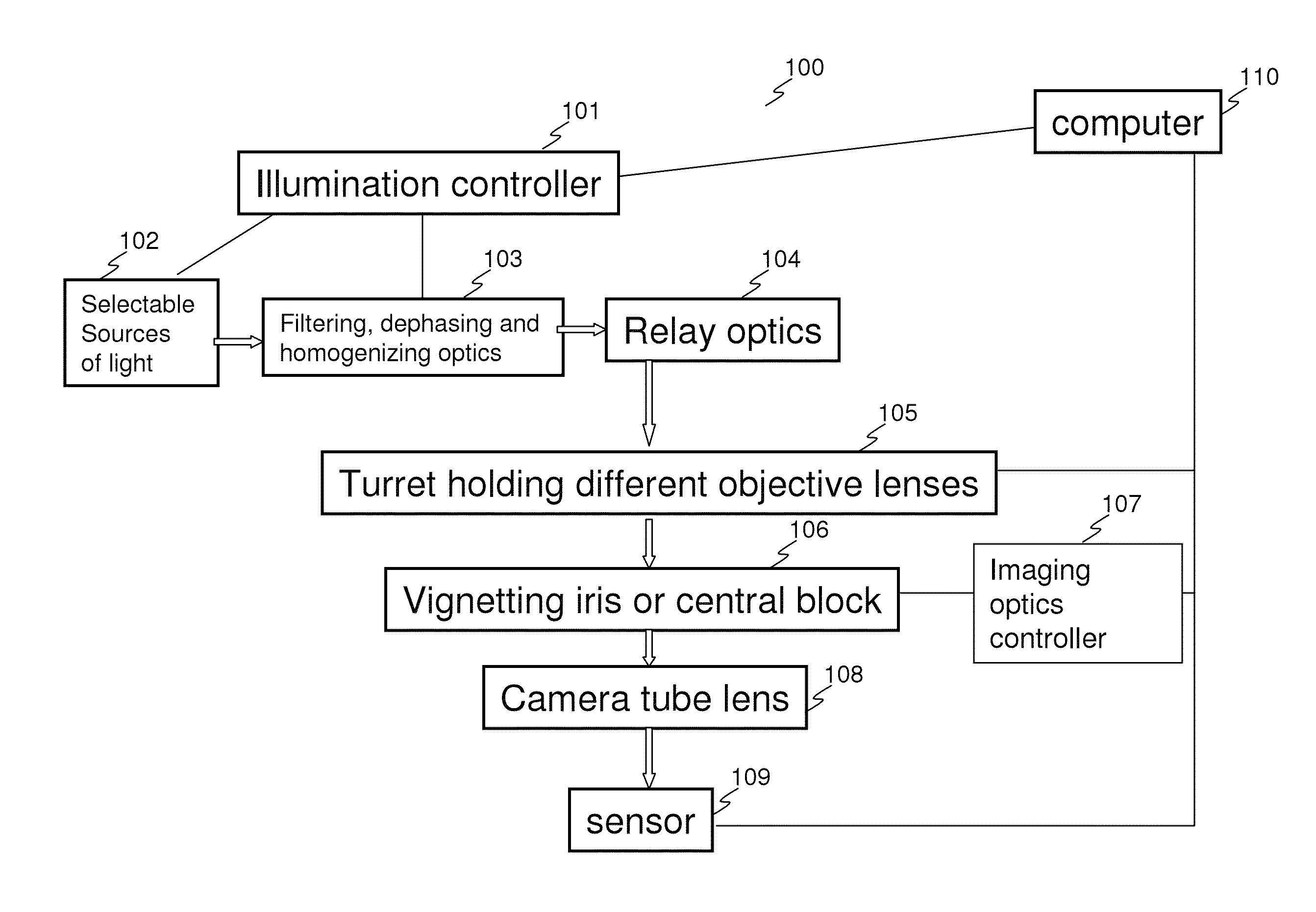
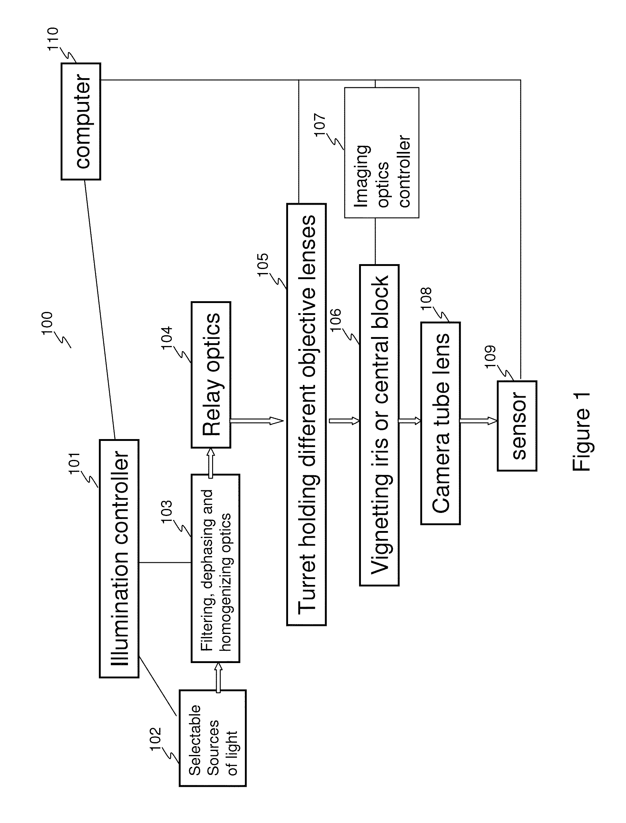
[0024]In the following detailed description, reference will be made to the accompanying drawing(s), in which identical functional elements are designated with like numerals. The aforementioned accompanying drawings show by way of illustration, and not by way of limitation, specific embodiments and implementations consistent with principles of the present invention. These implementations are described in sufficient details to enable those skilled in the art to practice the invention and it is to be understood that other implementations may be utilized and that structural changes and / or substitutions of various elements may be made without departing from the scope and spirit of present invention. The following detailed description is, therefore, not to be construed in a limited sense.

[0025]One or more embodiments of the present invention provide a fast optical (non-scanning) microscopy method and apparatus for selectively viewing object features, including object features buried under...


PUM


Abstract

System and method for selectively viewing features of objects, including features hidden under non-transparent materials. The system includes: illuminating light source producing illuminating light having controlled angular spectrum; homogenizing optics for spatial intensity modulation of illumination light; dephasing optics to reduce or suppress interference pattern in image due to the coherence of illumination light; infinity corrected objective directing the illuminating light on the object and collecting light from the object; illumination optical path delivering the illuminating light from the illuminating light source to infinity-corrected objective; relay optics for introducing necessary tilt angle for rays of the illuminating light entering the infinity corrected objective; adjustable iris vignetting free aperture of optical fiber; apodizing element within relay optics for spatial modulation of illumination intensity; image sensor for creating image of object; and imaging optical path for delivering light from object to image sensor, which includes tube lens, removable block and adjustable iris.

Description

BACKGROUND OF THE INVENTION[0001]1. Field of the Invention[0002]The present invention generally relates to systems and methods for optical imaging and, more specifically, to providing fast (non-scanning) optical microscopy method and apparatus for selectively viewing various object features, including features buried under non-transparent material.[0003]2. Description of the Related Art[0004]Viewing of object features buried under “nontransparent materials” represents a serious technical challenge, especially when the optical vision system must be capable of generating real time live images of the object and the object features do not transmit light. Scanning is not an acceptable solution in such vision systems and back light illumination cannot be used because the object features themselves do not transmit backlight. Moreover, the use of an illuminating light with a wavelength located within the material transparency window may sometimes not be practical due to cost considerations,...

Claims


Application Information

Patent Timeline
Patent Type & Authority Patents(United States)
IPC IPC(8): G02B21/36G01J3/46
CPCG01J1/0214G02B21/10G02B21/365G02B27/0018G01B9/04G01B11/24
Inventor BORDENYUK, ANDREY
Owner ORBOTECH LTD
Why Eureka
Try Eureka