
Integrated-type high step-up ratio DC-AC conversion circuit with auxiliary step-up circuit

a conversion circuit and step-up converter technology, applied in the direction of electric variable regulation, process and machine control, instruments, etc., can solve the problems of reducing reliability and efficiency, lowering the amplification of the step-up converter b>2/b>, and affecting the efficiency of the step-up converter, so as to reduce the cost of elements, increase the dc voltage, and reduce the effect of switching loss and conduction loss

Active Publication Date: 2013-03-05
NATIONAL TSING HUA UNIVERSITY
View PDF23 Cites 0 Cited by
  • Summary
  • Abstract
  • Description
  • Claims
  • Application Information

AI Technical Summary

Benefits of technology

The invention is a solution for improving the design of DC switches, which helps to decrease costs and increase efficiency. It uses an isolated Cuk integration unit and an auxiliary step-up unit to boost the DC voltage in a circuit. This helps to use low voltage switches and reduce the need for expensive high voltage power switches. The result is decreased switching and conduction loss, and improved overall circuit efficiency.

Problems solved by technology

Mass utilization of petroleum has generated enormous pollution and obviously changed the global ecological environment.
However, the above-mentioned two stages of voltage conversions greatly lower the reliability and efficiency.
However, the amplification of the step-up converter 2 is still insufficient.
Thus, the DC-AC conversion circuit can only apply to the cases having a higher-voltage DC power source.
If the switch does not have sufficient voltage resistance or current resistance, it may be damaged.
As the DC switches have to resist higher voltage, they usually have higher price, larger volume, greater switching loss and insufficient step-up ratios.
However, the step-up ratio and conversion efficiency are still insufficient.
Further, the current-limiting circuit occupies additional area.

Method used


Image

  • Integrated-type high step-up ratio DC-AC conversion circuit with auxiliary step-up circuit
  • Integrated-type high step-up ratio DC-AC conversion circuit with auxiliary step-up circuit
  • Integrated-type high step-up ratio DC-AC conversion circuit with auxiliary step-up circuit

Examples


Embodiment Construction

[0025]The technical contents of the present invention are described in detail in cooperation with the drawings below.

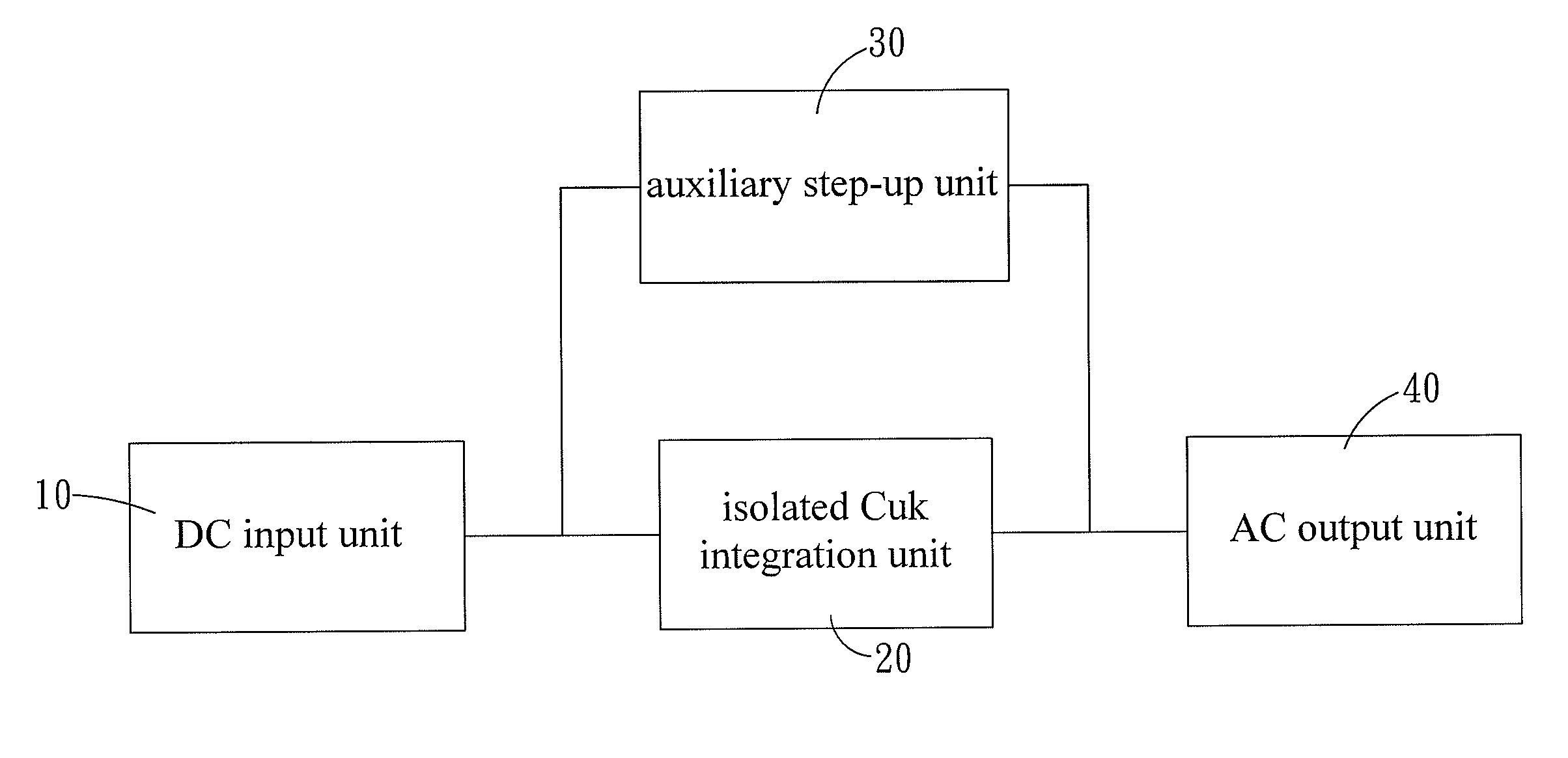
[0026]Refer to FIG. 3 and FIG. 4. FIG. 3 is a block diagram schematically showing the circuit architecture according to one embodiment of the present invention. FIG. 4 is a schematic view showing a circuitry according to one embodiment of the present invention. The present invention provides an integrated-type high step-up ratio DC-AC conversion circuit with an auxiliary step-up circuit, which comprises a DC input unit 10 providing a DC voltage; an isolated Cuk integration unit 20; an auxiliary step-up unit 30; and an AC output unit 40.

[0027]The isolated Cuk integration unit 20 converts the DC voltage into a high DC voltage. The isolated Cuk integration unit 20 further comprises a first inductor 21, a first DC-side switch 22, a first high-frequency transformer 23, a first capacitor 24 and a first diode 25. The first inductor 21 is connected to the DC input unit 10. Th...


PUM


Abstract

An integrated-type high step-up ratio DC-AC conversion circuit with an auxiliary step-up circuit applies to converting a low DC voltage of alternative energy into a high AC voltage. The conversion circuit uses an isolated Cuk integration unit and an auxiliary step-up unit to form a multi-phase input and uses parallel charging and cascade discharging to boost the DC voltage in the DC side with a low voltage power switches and low duty cycle and then converts the boosted DC voltage into AC voltage. The auxiliary step-up unit not only shares the entirety of power but also exempts the DC-side circuit from using high voltage power switches, whereby the cost of elements is reduced. Further, the conversion circuit can decrease the switching loss and conduction loss of the DC-side switches and promote the efficiency of the circuit.

Description

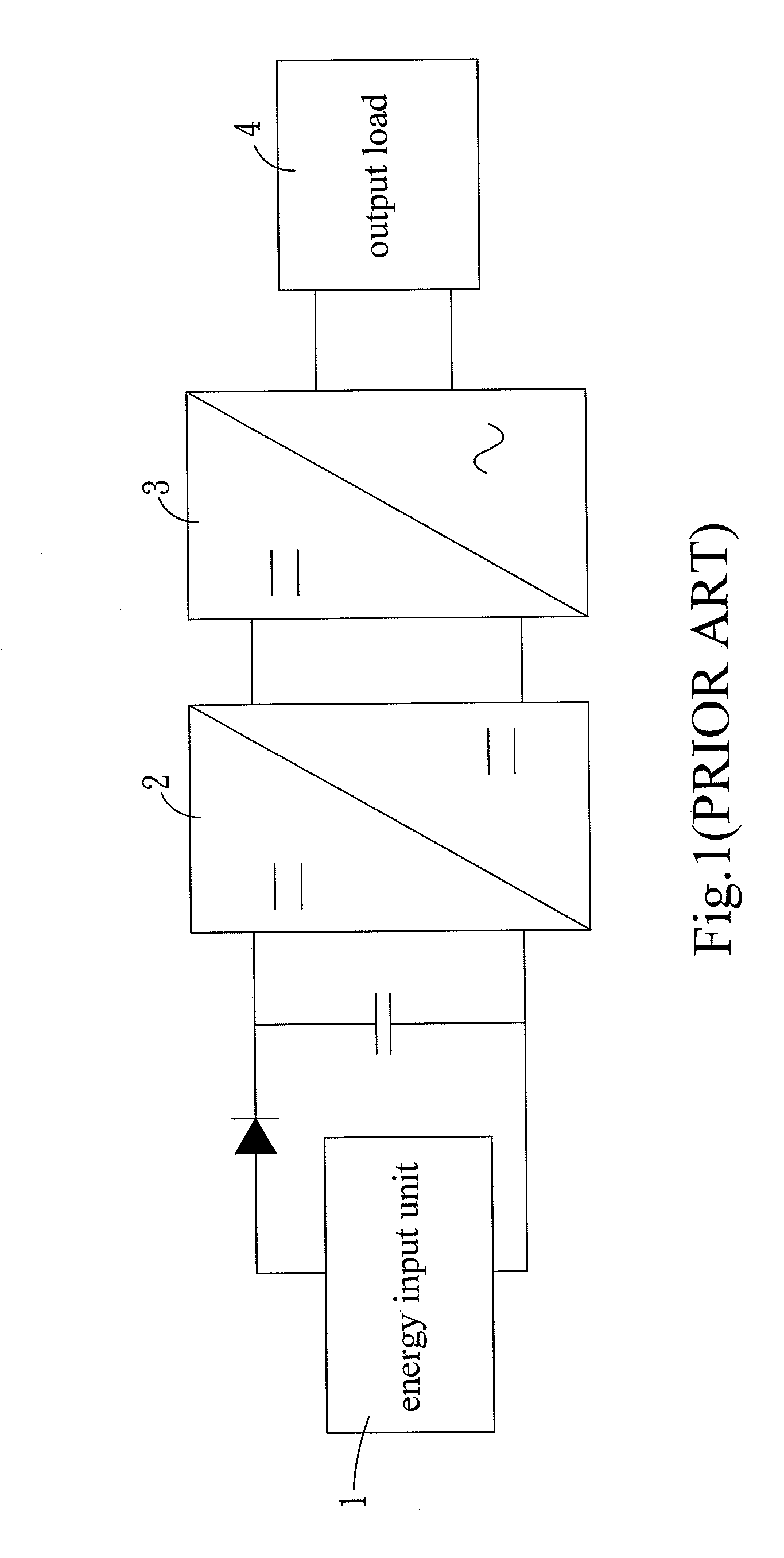
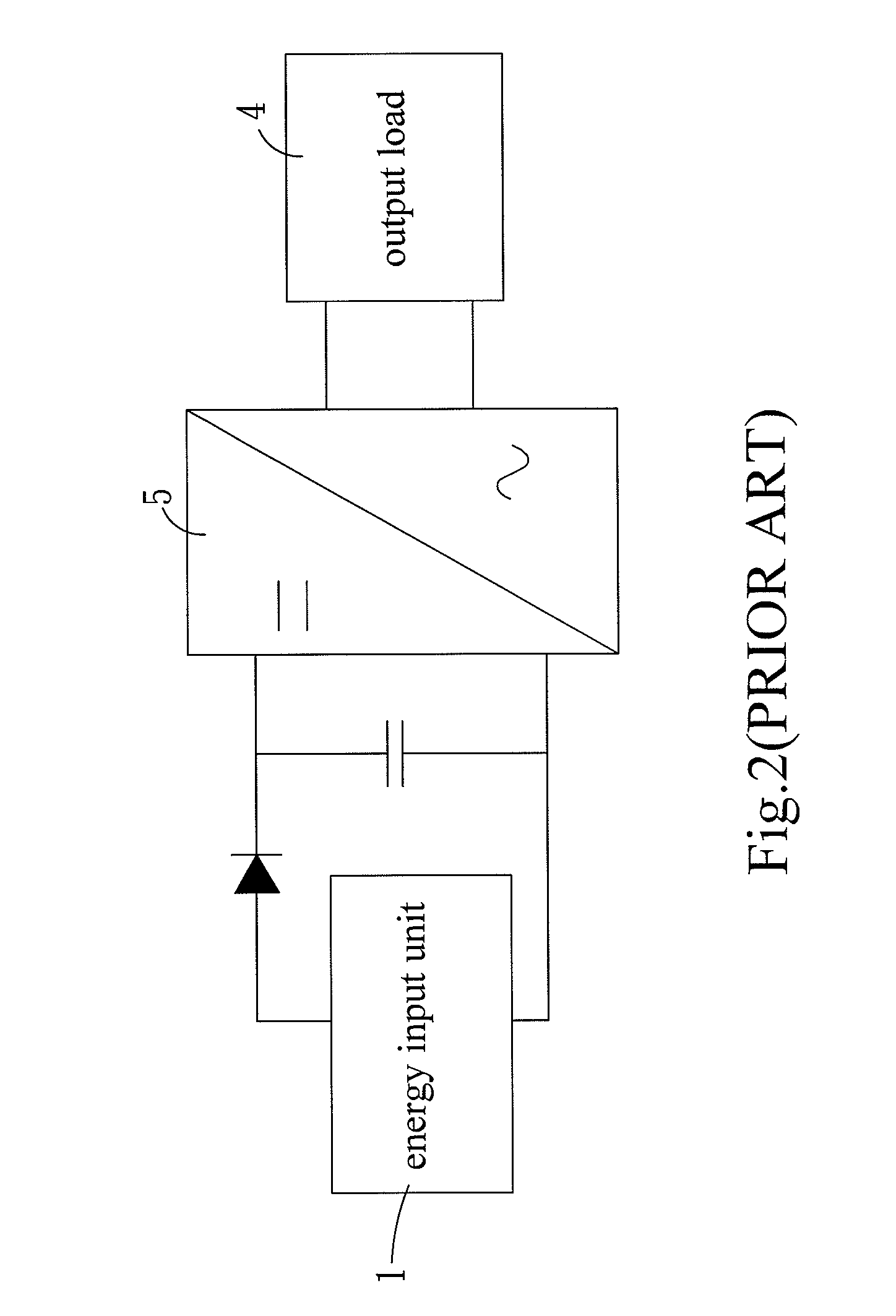
FIELD OF THE INVENTION[0001]The present invention relates to a DC-AC conversion circuit, particularly to an integrated-type high step-up ratio DC-AC conversion circuit with an auxiliary step-up circuit.BACKGROUND OF THE INVENTION[0002]Mass utilization of petroleum has generated enormous pollution and obviously changed the global ecological environment. It is also the primary factor causing climate change and global warming. Facing severe pollution caused by petroleum, many nations and large businesses have paid attention to develop alternative energy, such as solar energy. As to solar energy, the energy of sunlight is converted into DC current or DC voltage via photoelectric conversion. DC voltage must be converted into high-voltage AC voltage before it can apply to common household appliances.[0003]Refer to FIG. 1. A conventional DC-AC conversion circuit used in alternative energy system comprises a low-voltage energy input unit 1, a step-up converter 2, a DC-AC converter 3 and an ...

Claims


Application Information

Patent Timeline
Patent Type & Authority Patents(United States)
IPC IPC(8): H02M3/335
CPCH02M3/005H02M7/4807
Inventor PAN, CHING-TSAILAI, CHING-MING
Owner NATIONAL TSING HUA UNIVERSITY
Learn More