Method for laser interference lithography using diffraction grating

a laser interference lithography and diffraction grating technology, applied in the direction of microlithography exposure apparatus, instruments, photomechanical treatment, etc., can solve the problems of substantial inability to realize, destructive interference, and construction interference, and achieve the effect of simplifying the optical system, high resolution, and low coheren

Active Publication Date: 2013-03-19
LG CHEM LTD
View PDF8 Cites 3 Cited by
  • Summary
  • Abstract
  • Description
  • Claims
  • Application Information

AI Technical Summary

Benefits of technology

[0031]According to the present invention, since a laser beam is inputted perpendicularly to a diffraction grating and thus ±1st diffracted lights are used for laser interference lithography, it is possible to realize an interference pattern with higher resolution than a conventional case. Also, this method allows to use a light source with low coherence, and enables mass production by simplifying an optical system and thus enhancing process convenience.

Problems solved by technology

As well known in the art, a wave causes constructive interference at a position with the same phase and destructive interference at a position with different phases.
However, in case the interference angle is 90 degrees, the laser is guided in parallel with the upper surface of the photoresist layer, so its actual realization is substantially considered as being impossible.
However, due to the physical limit, it is practically impossible to make a diffraction mask having a grating period that is ½ or less of the wavelength of the laser source.
In addition, since the intensity of light causing constructive interference is decreased due to the total reflection in the prism 4, the degree of definition of the fine pattern is deteriorated.
Also, the immersion interference lithography using a prism demands an additional device for immersion, so the equipment for alignment of optical systems are required and thus it is not suitable for mass production.

Method used


Image

  • Method for laser interference lithography using diffraction grating
  • Method for laser interference lithography using diffraction grating
  • Method for laser interference lithography using diffraction grating

Examples


Embodiment Construction

[0070]Hereinafter, the present invention is explained in more detail using an experimental example. However, the following experimental example is for illustration purpose only, not intended to limit the scope of the present invention.

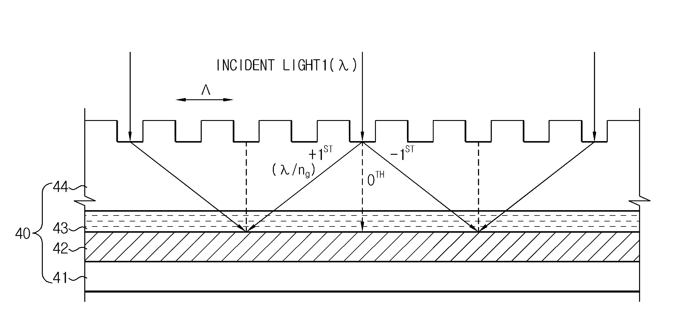
[0071]In this experimental example, a diffraction grating was prepared with the same configuration as the diffraction grating shown in FIG. 6. First, a glass substrate was prepared, and a BARC was formed on an upper surface of the glass substrate. Also, a repeated grating pattern was formed on the glass substrate with the BARC by means of photoresist. The repeated grating pattern of the diffraction grating shown in FIG. 6 was formed by etching of SiO2. Meanwhile, in this experimental example, a photoresist material having low durability but not giving serious problem in actual optical features was used to form the grating pattern.

[0072]FIG. 7 is a photograph showing the diffraction grating prepared suitably for the conditions proposed in this experimen...


PUM

PropertyMeasurementUnit
interference angleaaaaaaaaaa
refractive indexaaaaaaaaaa
wavelengthaaaaaaaaaa

Abstract

A method for laser interference lithography using a diffraction grating includes (a) forming a photoresist layer on a work substrate to which a repeated fine pattern is to be formed; (b) forming a refractive index matching material layer on the photoresist layer; (c) forming on the refractive index matching material layer a diffraction grating layer having a period of diffraction grating within the range from λ / ng to λ / n0 (λ is a wavelength of laser beam, ng is a refractive index of the diffraction grating, and n0 is a refractive index in the air or in vacuum); and (d) exposing the photoresist layer by means of mutual interference of positive and negative diffracted lights with the same absolute value by inputting a laser beam perpendicularly to the diffraction grating layer. This method allows to realize an interference pattern with higher resolution and to use a laser source with lower coherence.

Description

[0001]This application is a 35 U.S.C. §371 National Stage entry of International Application No. PCT / KR2008 / 005892, filed on Oct. 8, 2008, and claims priority to Korean Application No. 10-2007-0104584, filed on Oct. 17, 2007, which are all hereby incorporated by reference in their entireties.TECHNICAL FIELD[0002]The present invention relates to a method for laser interference lithography using a diffraction grating, and more particularly to a method for laser interference lithography using a diffraction grating, which may implement a high resolution (sub-micrometer) pattern using interference of positive and negative diffracted lights with the same absolute diffracted value in a diffraction grating by inputting a laser source perpendicularly to the diffraction grating.BACKGROUND ART[0003]Generally, laser interference lithography is a technique for conducting exposure to light by using an interference pattern occurring in an overlap region of light with high coherence, which has seve...

Claims


Application Information

Patent Timeline
Patent Type & Authority Patents(United States)
IPC IPC(8): G03F7/20
CPCG03F7/70408G02B5/1809G02B5/1814
Inventor KIM, TAE-SUKIM, JAE-JINSHIN, HYUN-WOO
Owner LG CHEM LTD
Why Eureka
Try Eureka