Flux focusing arrangement for permanent magnets, methods of fabricating such arrangements, and machines including such arrangements

a technology of permanent magnets and focusing arrangements, applied in the field of permanent magnets, can solve the problems of increasing the number of magnetic materials, increasing the cost of high-energy density materials, and reducing the efficiency of magnetic materials, so as to reduce the risk of affecting the performance of magnetic materials, and reduce the cost of high-energy materials.

Active Publication Date: 2013-03-19
BWP GRP
View PDF49 Cites 47 Cited by
  • Summary
  • Abstract
  • Description
  • Claims
  • Application Information

AI Technical Summary

Benefits of technology

[0009]Numerous arrangements for permanent magnets are disclosed that can focus the flux produced by the magnets. Depending on the particular application in which the disclosed designs and techniques are used, efficiency and reliability may be increased by minimizing flux leakage, increasing peak flux density, and shaping the flux fields to improve the effective coercivity of the flux focusing permanent magnet arrangement when loaded, and to achieve customized voltage and current waveforms.

Problems solved by technology

Such machines are generally the lowest cost and lightest weight permanent magnet machines, but they typically suffer from limitations in performance that can be traced to the flux density limitations, well known in the art, of conventionally designed and manufactured permanent magnets.
High magnetic energy density materials, such as the neodymium-iron-boron system, are typically more expensive and have historically been subject to significant price volatility.
Thicker magnets require more magnetic material, and cost generally scales with the amount of materials.
Thus, increasing flux density for such machines with these approaches increases cost and potentially increases cost volatility, and may yield only limited performance improvements.
Further, there is an inherent limit to the amount of flux in a given magnetic circuit, where further additions to magnet thickness may yield little to no additional flux.

Method used


Image

  • Flux focusing arrangement for permanent magnets, methods of fabricating such arrangements, and machines including such arrangements
  • Flux focusing arrangement for permanent magnets, methods of fabricating such arrangements, and machines including such arrangements
  • Flux focusing arrangement for permanent magnets, methods of fabricating such arrangements, and machines including such arrangements

Examples


Embodiment Construction

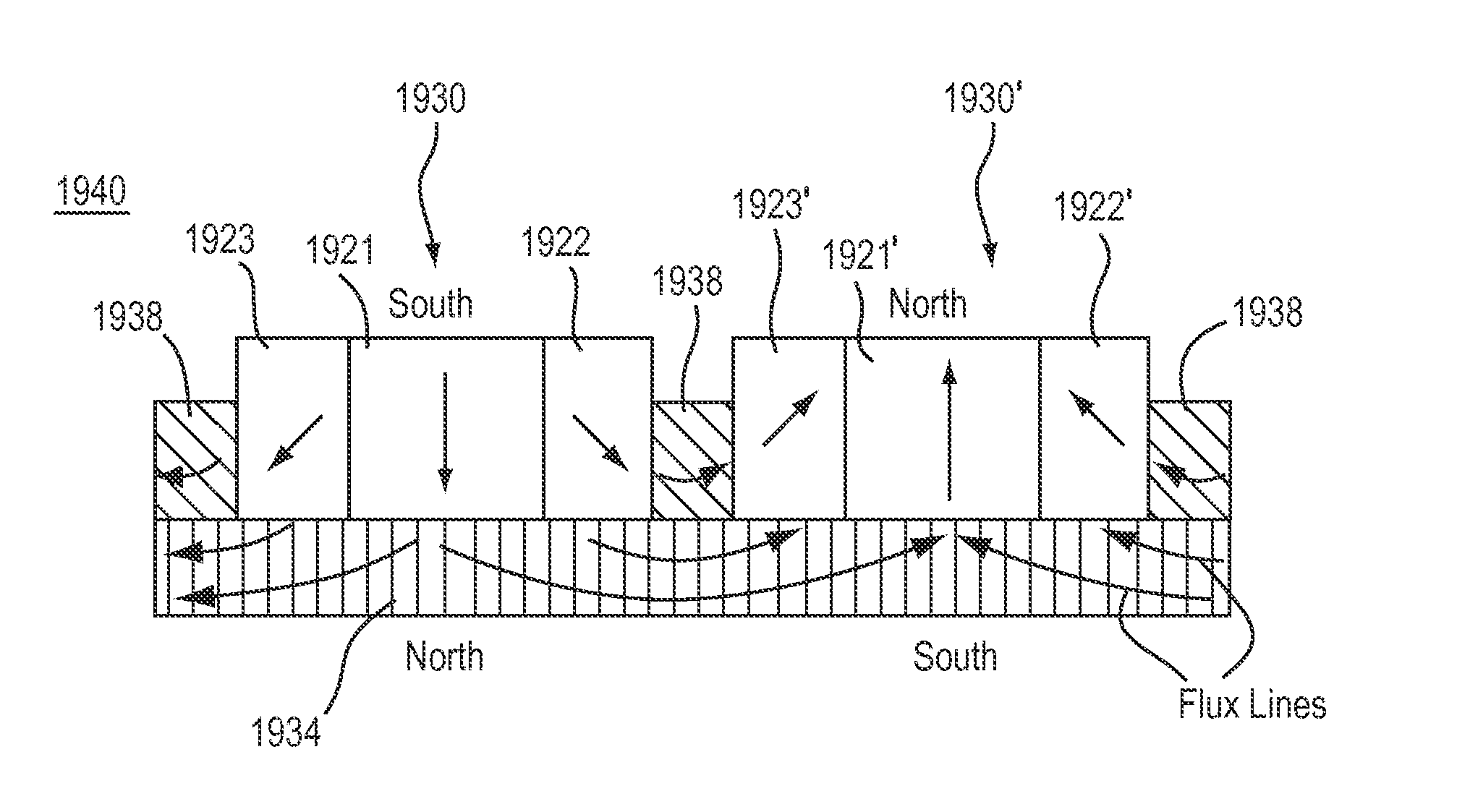
[0061]The flux focusing magnet assemblies described below may be beneficially used in any application that utilizes magnetic flux, and are particularly useful in those applications where it is desired to maximize the flux that crosses a gap while minimizing leakage flux, improving the peak flux density across the gap, and / or shaping the flux field across said gap.

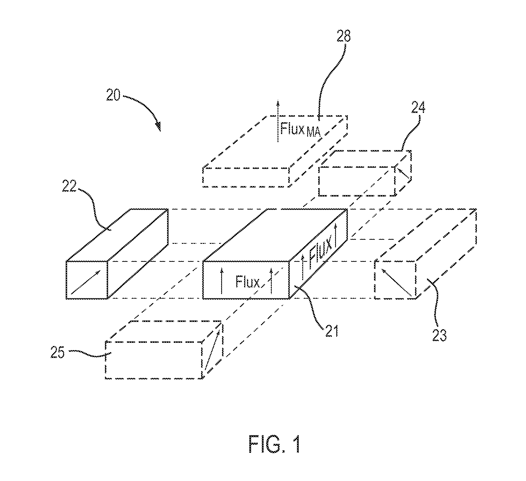
[0062]A flux focusing magnet assembly 20 is illustrated schematically in FIG. 1. Magnet assembly 20 includes a first magnet 21 and a second magnet 22 disposed adjacent to first magnet 21. The magnetic domains in each magnet are aligned parallel to a respective nominal flux axis, each represented in FIG. 1 by one or more arrows, which for the first magnet 21 are labeled “Flux,” with the head of each arrow having the same polarity (e.g. north or south). As shown in FIG. 1, the nominal flux axes of magnets 21 and 22 are not parallel, but are oriented towards each other, to converge in a direction above the magnets. As the arti...


PUM

PropertyMeasurementUnit
angle of polarizationaaaaaaaaaa
angleaaaaaaaaaa

Abstract

Numerous arrangements for permanent magnets are disclosed that can focus the flux produced by the magnets. Depending on the particular application in which the disclosed designs and techniques are used, efficiency and reliability may be increased by minimizing flux leakage, increasing peak flux density, and shaping the flux fields to improve the effective coercivity of the flux focusing permanent magnet arrangement when loaded, and to achieve customized voltage and current waveforms. The disclosed magnet assemblies may be incorporated into a machine, such as a motor / generator, having windings and may be disposed for movement relative to the windings. The magnet assembly may be mounted on a support formed of one or more ferromagnetic materials, such as a back iron The disclosed flux focusing magnet assemblies may be formed using a variety of manufacturing methods.

Description

PRIORITY[0001]This application claims the benefit of U.S. Provisional Application Ser. No. 61 / 517,086, filed Apr. 13, 2011, the disclosure of which is incorporated herein by reference.FIELD OF THE INVENTION[0002]The disclosure relates to the field of permanent magnets, including the use of permanent magnets and permanent magnet arrangements in machinery and other devices.BACKGROUND OF INVENTION[0003]Permanent magnet electromagnetic machines (referred to as permanent magnet machines herein) utilize magnetic flux from permanent magnets to convert mechanical energy to electrical energy or vice versa. Various types of permanent magnet machines are known, including axial flux machines, radial flux machines, and transverse flux machines, in which one component rotates about an axis or translates along an axis, either in a single direction or in two directions, e.g. reciprocating, with respect to another component. Such machines typically include windings to carry electric current through ...

Claims


Application Information

Patent Timeline
Patent Type & Authority Patents(United States)
IPC IPC(8): H02K21/12H02K1/27
CPCH02K1/2766H02K1/278H02K1/2786H02K1/2793H02K21/12H02K21/145H01F7/0278H01F7/0205H02K21/24Y10T29/49009F16C32/04Y10T29/49012Y10T29/49078H02K1/2791H01F7/021H02K1/27
Inventor SMITH, JAMES S.PILLSBURY, ROBERTSULLIVAN, BRIAN
Owner BWP GRP
Why Eureka
Try Eureka