Thick targets for transmission x-ray tubes

a technology of transmission x-ray and target, which is applied in the direction of x-ray tube target materials, x-ray tube target and convertor, x-ray tube, etc., can solve the problems of large average number of collisions experienced by an electron until it is effectively stopped, too much dose to patients in medical x-rays,

Active Publication Date: 2013-03-26
NANORAY BIOTECH CO LTD
View PDF17 Cites 35 Cited by
  • Summary
  • Abstract
  • Description
  • Claims
  • Application Information

AI Technical Summary

Problems solved by technology

Yet there is still significant low energy x-ray generation which cause still too much dose to patients in medical x-rays, or provide unwanted low energy x-rays which must be removed in applications such using x-ray tubes for x-ray microscopy, x-ray fluorescence or x-ray diffraction wherein the lower x-rays must be removed.
For larger initial energies, or thick geometries, the average number of collisions experienced by an electron until it is effectively stopped becomes very large, and detailed simulation is very inefficient.
PENELOPE is thus not capable of providing reliable simulations when a thick transmission target is involved or when the accelerating voltages for the impinging electrons exceed 100 kVp.
Hence there is no reliable simulation tool to predict the results of using thick transmission targets, especially when those targets may use accelerating voltages above about 100 kVp.
In medical applications low energy x-radiation is absorbed by the patient without producing useful images and hence becomes unwanted additional dose.
Yet the monochromatic component of the wide energy band x-rays produced with conventional reflection and transmission x-ray tube sources requires considerable effort and expense to convert to useful monochromatic x-rays.
When there is a considerable amount of low energy x-radiation, the cost of producing monochromatic x-ray energies increases.
Such filters reduce proportionally more low energy x-rays than higher useful x-rays however there is a limit of how much x-rays can be filtered before, the focal spot size that can be obtained and the amount of energy that can be removed from the spot on the target where the beam impinges cause damage to the target.

Method used


Image

  • Thick targets for transmission x-ray tubes
  • Thick targets for transmission x-ray tubes
  • Thick targets for transmission x-ray tubes

Examples


Embodiment Construction

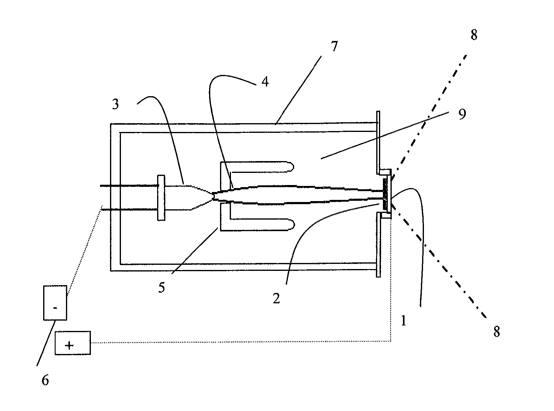
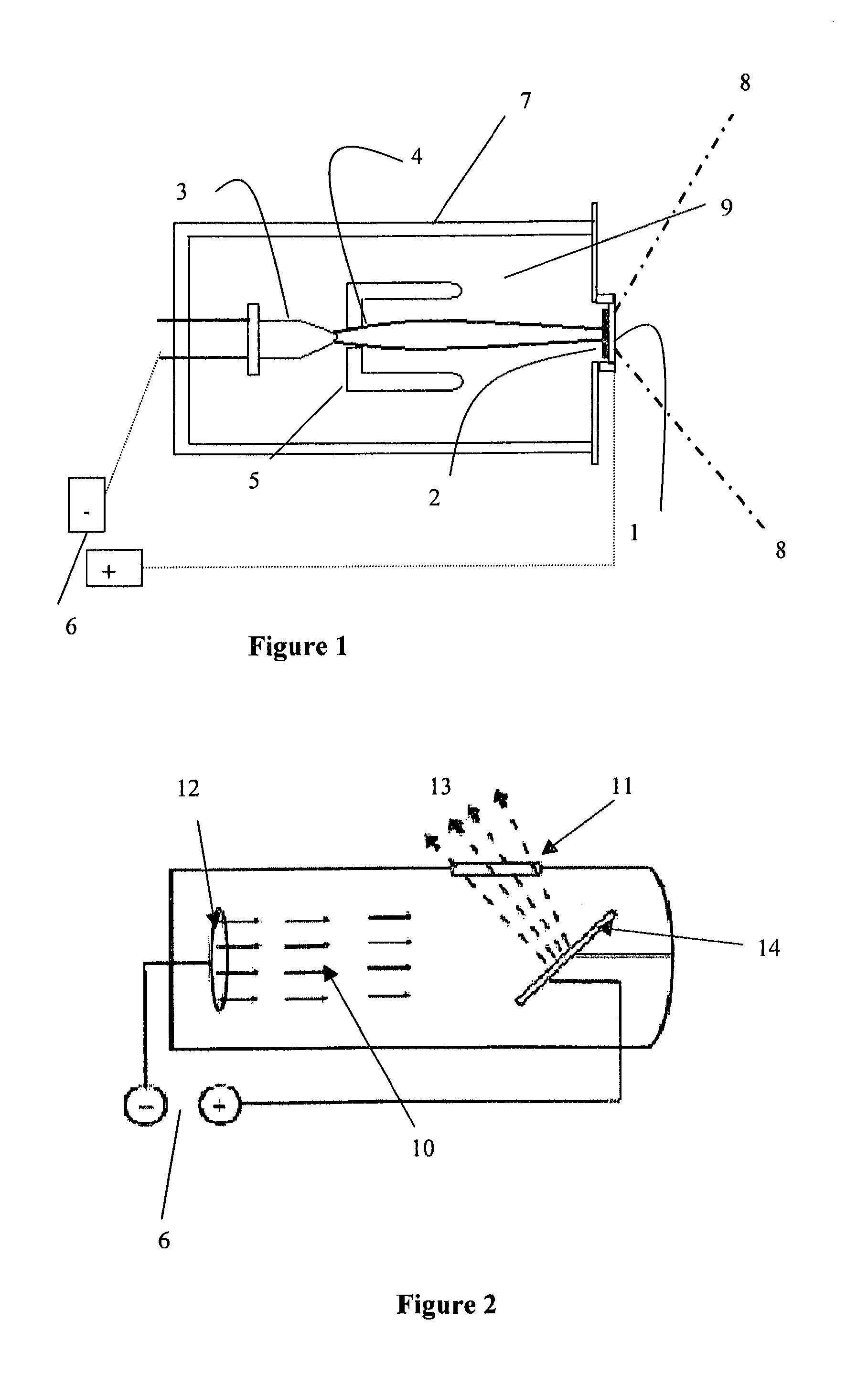
[0031]Open transmission tubes are typically used for imaging of electronic circuits as well as other high-resolution applications and may alternatively be used as the x-ray source when high multiplication factors are required of the object's image. Closed tubes are sealed with a vacuum whereas open or “pumped down” tubes have a vacuum pump continuously attached drawing a vacuum as the tube is used usually to allow for frequent replacement of tube parts which tend to fail in operation. For purposes of this invention transmission tubes include both open and closed transmission type tubes except as otherwise stated.

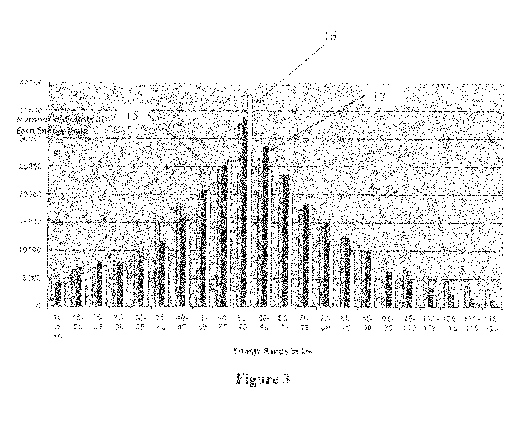
[0032]Unless otherwise specified x-ray tube spectral data was taken with an Amptek Model XR-100 with a CdTe sensor 1 mm thick and 10 mils of Be filter. The sensor was placed at a distance of 1 meter from the x-ray tube and a tungsten collimator with a collimator hole of 100 μm diameter placed in front of the sensor. Various tube currents and exposure times were used but comp...


PUM


Abstract

This invention relates to the use of thick target materials 50 microns and thicker for an x-ray transmission tube; to possible target material compositions including various elements and their alloys, eutectic alloys, compounds, or intermetallic compounds; and applications for utilizing such thick target transmission x-ray tubes. The target comprises at lease one portion of the target with a thickness of 50 microns or greater. The target can be optionally attached to a substrate end-window essentially transparent to x-rays or be thick enough so that no such substrate is required. Applications include producing a high percentage of monochromatic line mission x-rays of said thick target for use in reduced dose medical imaging and other non-destructive testing applications.

Description

FIELD OF THE INVENTION[0001]This invention generally refers to an improved way of producing x-rays from a transmission x-ray tube which significantly reduces unwanted low energy x-rays while proportionally enhancing higher energy characteristic line emissions from the target. Specifically it relates to using thick transmission targets, greater than about 50 microns. The invention includes various applications of the invention in various medical and dental imaging, fluoroscopy, and non-destructive testing applications.DESCRIPTION OF RELATED ART[0002]U.S. Pat. No. 7,180,981 dated Feb. 20, 2007, enclosed herein its entirety for reference, discloses end window x-ray tubes with target foils up to a maximum of 41 microns thick. 41 microns of target material offers filtering of some of the x-rays generated in the low energy range depending on the target material used. Yet there is still significant low energy x-ray generation which cause still too much dose to patients in medical x-rays, o...

Claims


Application Information

Patent Timeline
Patent Type & Authority Patents(United States)
IPC IPC(8): H01J35/00
CPCH01J35/08H01J35/18H01J2235/081H01J2235/087H01J35/116H01J35/186
Inventor WANG, CHIA-GEEPARSONS, BRUCE BRIANT
Owner NANORAY BIOTECH CO LTD
Why Eureka
Try Eureka