
Circuit assembly for controlling an optical system to generate optical pulses and pulse bursts

a circuit assembly and optical system technology, applied in the field of pulsed lasers, can solve the problems of low quality of machined surface and micro-cracks, unsatisfactory thermal side effects, and high cost of femtosecond lasers

Active Publication Date: 2013-04-02
INSTITUT NATIONAL D'OPTIQUE
View PDF18 Cites 8 Cited by
  • Summary
  • Abstract
  • Description
  • Claims
  • Application Information

AI Technical Summary

Problems solved by technology

However, such long pulses can cause heating, melting and vaporization of the target material, which leads to undesired thermal side-effects such as low quality of the machined surface and micro-cracks.
However, femtosecond lasers are often complex and expensive.
In addition, the ablation process is inherently slow, since the layer which is removed is usually very thin compared to that obtained using thermal ablation with longer pulses.
Usually, such designs suffer from a lack of flexibility since they require a tuning of the filter bandwidth to change the pulse duration.
However, the timing between successive pulses cannot be adjusted arbitrarily; it is rather determined by the harmonics of the laser cavity and the fundamental pulse repetition frequency.
Additionally, tunable pulse durations of a few tens of picoseconds are difficult to obtain, since complex pulse shaping mechanisms occur along the pulse propagation within the fiber laser cavity.
In addition, such diodes offer very little control on the amplitude of the emitted pulses, which are often followed by relaxation oscillations.
)), most schemes relying on solid-state lasers provide very limited or no tuning of the pulse repetition rate and pulse duration.
In addition, solid-state lasers lack the near diffraction-limited beam quality that sets apart fiber lasers and amplifiers from other types of laser sources.
However, the minimum pulse width of this source cannot reach the picosecond regime as it is limited to 1 ns, with rise time between 1 ns and 3 ns and even longer fall time.
However the disclosed source is a bulky free space laser, the pulse width range covered by this source is limited from 60 ps to 300 ps and the repetition rate is as low as 10 kHz, with no bursting capabilities.

Method used


Image

  • Circuit assembly for controlling an optical system to generate optical pulses and pulse bursts
  • Circuit assembly for controlling an optical system to generate optical pulses and pulse bursts
  • Circuit assembly for controlling an optical system to generate optical pulses and pulse bursts

Examples


Embodiment Construction

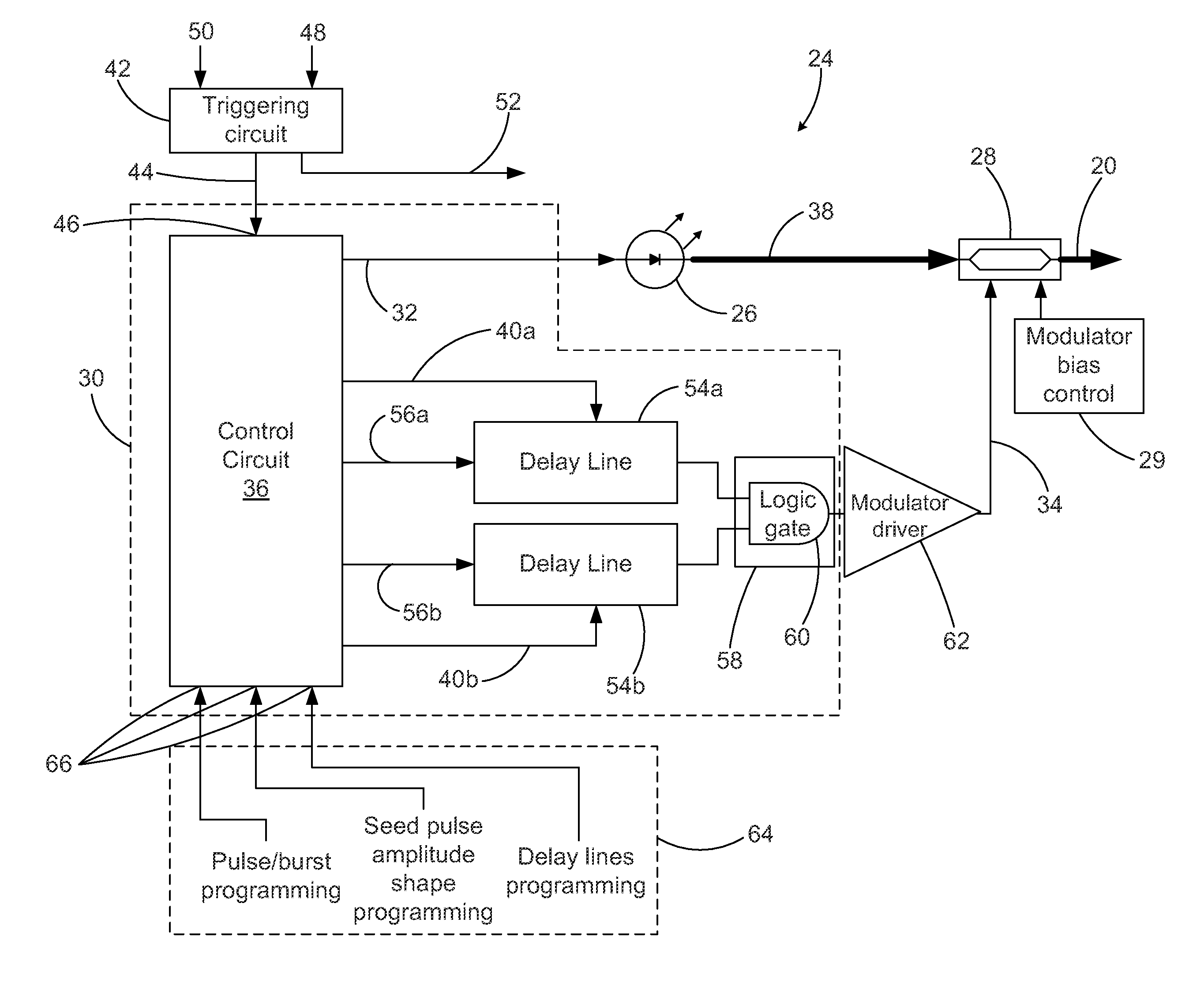
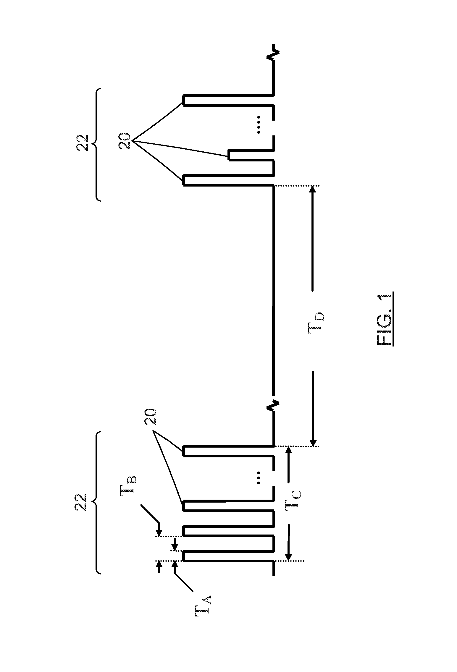
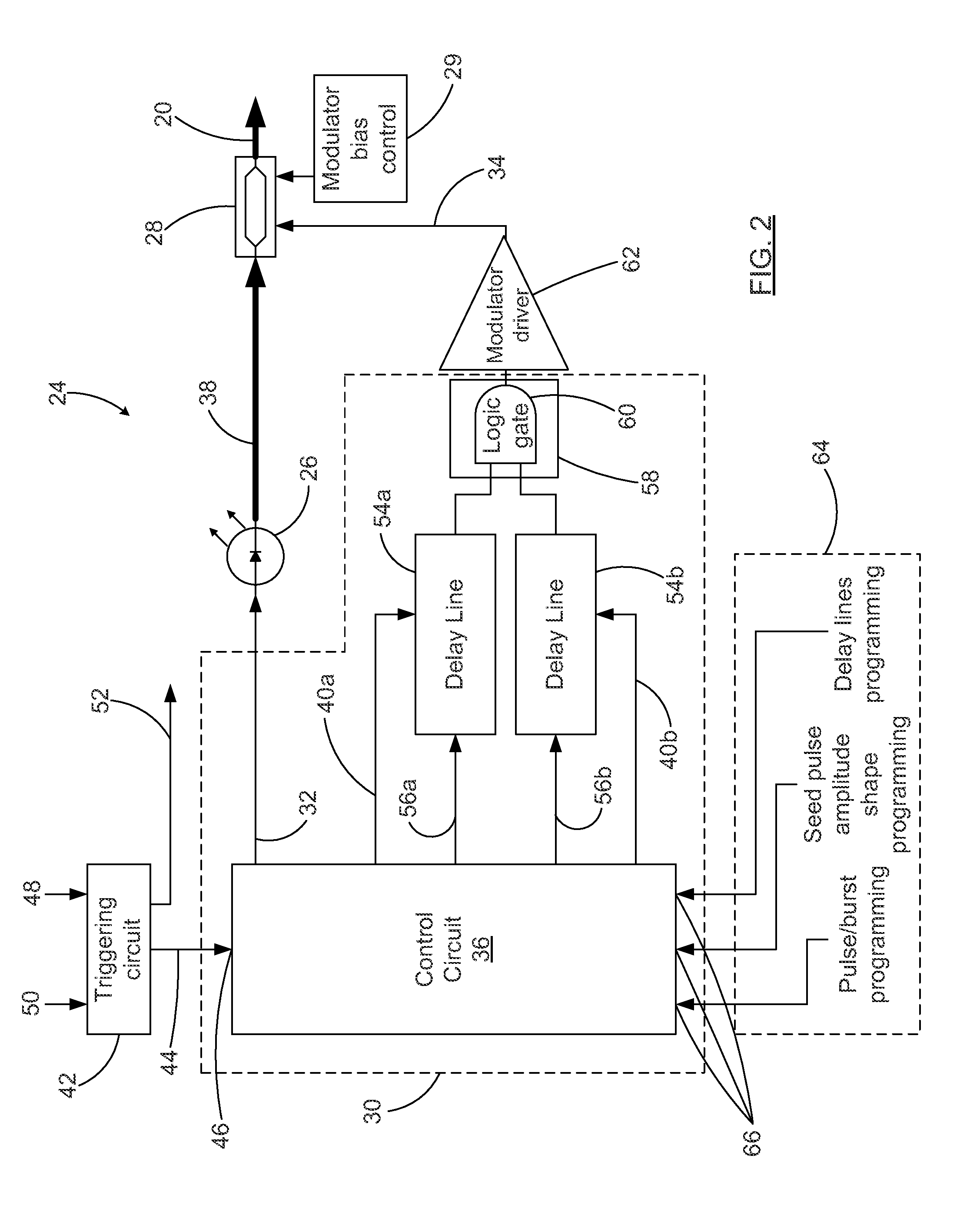
[0043]The present invention provides devices and method generating optical pulses, and may be particularly advantageous for generating optical pulses of duration in the picosecond range. Embodiments of the present invention generally involve the generation of a seed optical pulse by a pulsed light source, and the modulation of the seed optical pulse by an amplitude modulator. The timing of the opening and closing of the amplitude modulator with respect to the arrival of the seed optical pulse thereat will determine the final shape of the optical pulses. The present invention provides a circuit assembly allowing the generation of fast electrical pulses for driving the amplitude modulator, as will be described further below. In some embodiments, the amplitude modulator may “chop” the seed optical pulses in several sub-pulses, so that each seed pulse can result in one burst of sub-pulses.

[0044]In the description below, the embodiments presented are based on the use of a laser within a ...


PUM


Abstract

A circuit assembly controlling an optical system to generate optical pulses is provided. The optical system includes a seed light source optically coupled to an amplitude modulator. The circuit assembly includes a control circuit which generates a pulsed seed drive signal for driving the seed laser source, as well as logic signals defining successions of ON and OFF states and having a predetermined relative timing relationship. One or more of the logic signals is delayed by a corresponding programmable delay line to adjust the relative timing relationship between the logic signals. A logic gating module combines the logic signals according to one or more logical rule, thereby providing a modulator drive signal. Using this circuit assembly, the optical system outputs an optical pulse at each ON state of the modulator drive signal synchronized with the passage of one of the seed optical pulses through the amplitude modulator.

Description

FIELD OF THE INVENTION[0001]The present invention generally relates to pulsed lasers and other light sources and more particularly concerns an optical system and circuit assembly therefor capable of generating optical pulses in the picosecond range, with tunable repetition rate, amplitude and duration.BACKGROUND[0002]High power pulsed fiber lasers are currently in demand for a number of applications and uses. For example, numerous material processing applications such as memory repair, milling, micro-fabrication, drilling, etc. require pulsed laser systems which provide, among other requirements, high pulse energy, excellent pulse amplitude stability and beam quality, narrow linewidth and great flexibility in terms of control of the pulse amplitude and temporal duration, such as pulse to pulse control over the temporal duration at high (>100 kHz) repetition rates. Pulse bursting with in-burst pulse rate >100 MHz is also desirable.[0003]The temporal duration of laser pulses is ...

Claims


Application Information

Patent Timeline
Patent Type & Authority Patents(United States)
IPC IPC(8): H01S3/00
CPCH04B10/508G02F1/0121G02F2203/54
Inventor JACOB, MICHELDESBIENS, LOUISSISTO, MARCO MICHELE
Owner INSTITUT NATIONAL D'OPTIQUE
Learn More