Aircraft assembly

a technology for aircraft and components, applied in the direction of aircraft static dischargers, screws, threaded fasteners, etc., can solve the problems of affecting the reliability of aircraft, the risk of lightning current being easily destroyed, and the conveying capacity of lightning current without being destroyed, so as to achieve high reliability, improve reliability, and not easily destroyed

Active Publication Date: 2013-04-09
MITSUBISHI HEAVY IND LTD
View PDF13 Cites 13 Cited by
  • Summary
  • Abstract
  • Description
  • Claims
  • Application Information

AI Technical Summary

Benefits of technology

[0010]The present invention has been conceived in light of the above-described circumstances, and an object thereof is to provide an aircraft assembly provided with a lightning protection structure that is not easily destroyed by lightning current and that is highly reliable.
[0032]In addition, the insulating washer and the insulating spacer are interposed between the fixture and the structural member, thereby making it possible to improve reliability by double insulation.

Problems solved by technology

However, with the disclosure of U.S. Pat. No. 4,630,168, specification, the insulating caps are positioned at the surface of the skin, and there is a problem in that, when lightning current flows along the surface, the lightning current has to flow around these insulating caps, and the flow of the lightning current is thus obstructed.
In addition, the configuration in the disclosure of U.S. Pat. 5,845,872, specification is such that only one metal foil layer is provided as the conductive layer for dispersing lightning current; therefore, there is a risk of it being easily destroyed by the lightning current.
Furthermore, there is a problem with a metal foil in that, although it depends on the thickness thereof, the conveying capacity for conveying the lightning current without being destroyed is small.

Method used


Image

  • Aircraft assembly
  • Aircraft assembly
  • Aircraft assembly

Examples


Embodiment Construction

[0038]An embodiment according to the present invention will be described below, referring to the drawings.

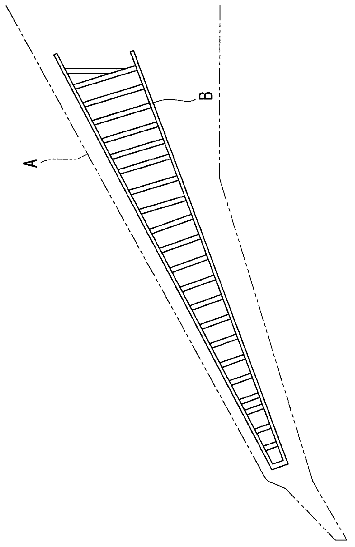
[0039]FIG. 1 shows a plan view of a main wing (aircraft assembly) A of an aircraft. A rib line B includes a position at which a shear-tie (structural member) 11, described later, is disposed, and shows a region where copper paint (conductive resin layer) 19 or a copper foil (conductive foil) 13, described later, is disposed.

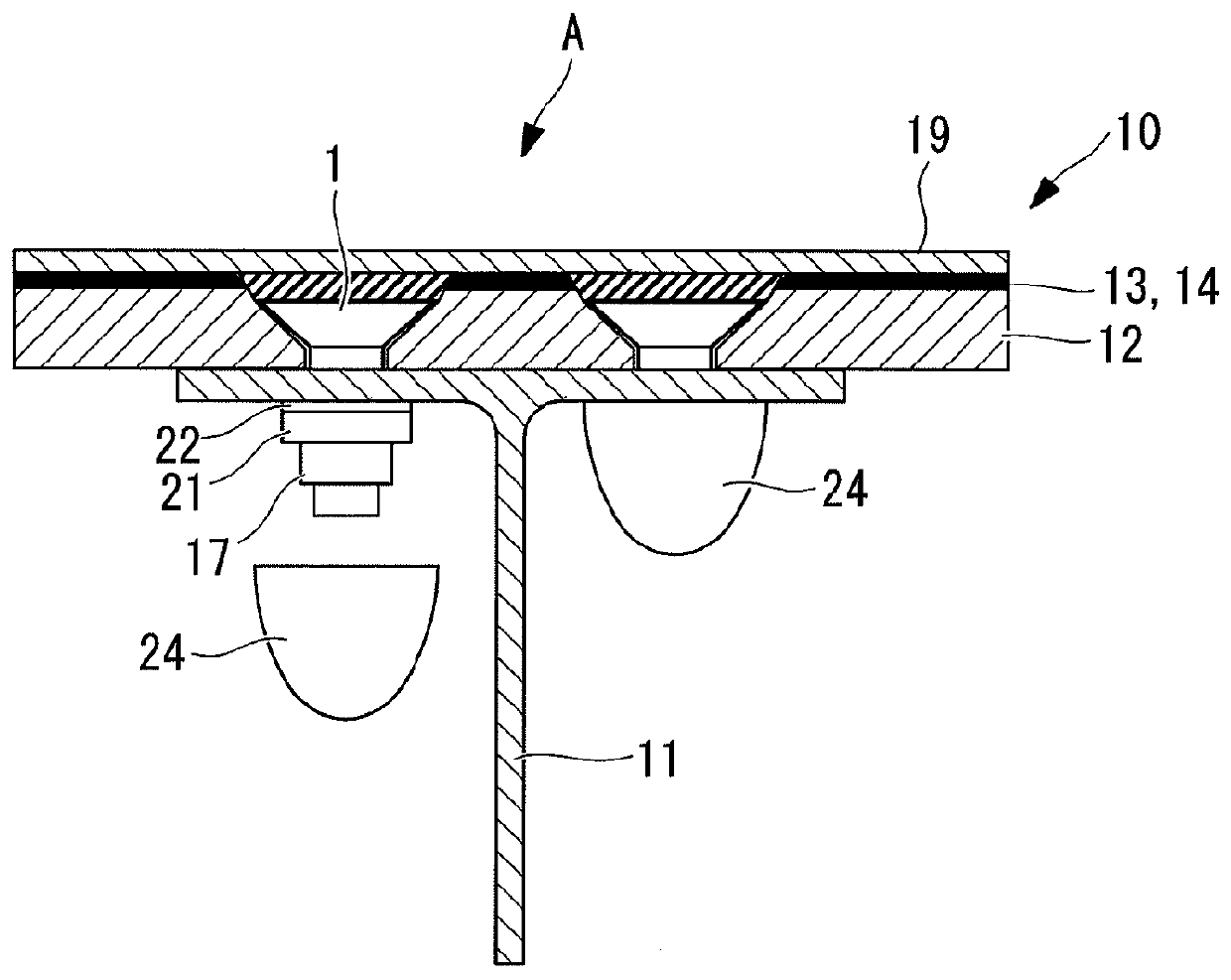
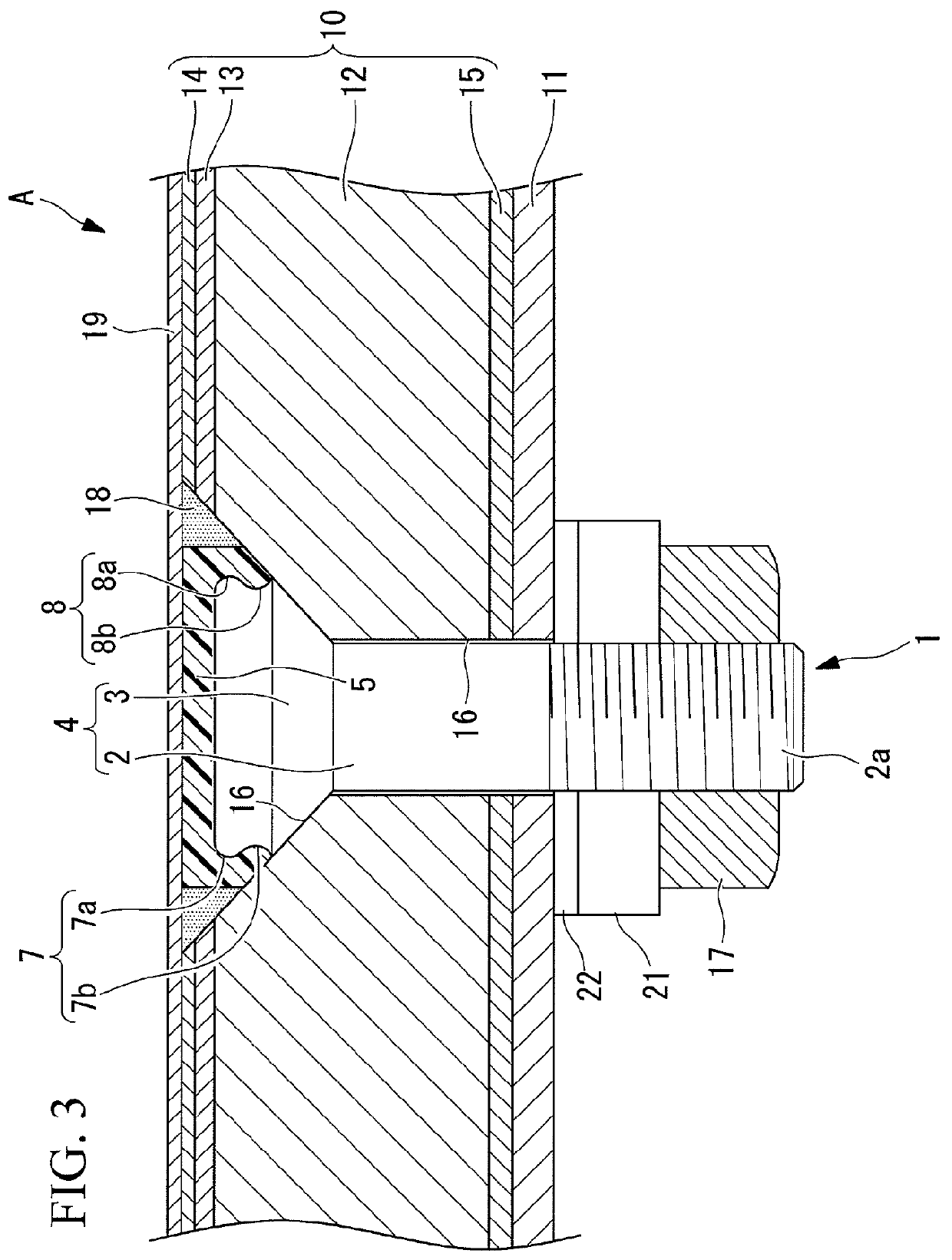
[0040]FIG. 2 schematically shows the positional relationship between a skin 10 and the shear-tie (Sea-Tie) 11. The shear-tie 11 is a member that joins the skin 10 and a stringer, a rib, and so on, and is assumed to be of a conductive material, such as aluminum alloy or titanium ally, or CFRP (carbon-fiber reinforced plastic). The skin 10 and the shear-tie 11 are fixed with a fastener 1. Specifically, a collar (nut) 17 is screwed on the tip of the fastener 1, thereby fastening the skin 10 and the shear-tie 11 to secure them together.

[0041]An insulating washer ...


PUM

PropertyMeasurementUnit
diameteraaaaaaaaaa
thicknessaaaaaaaaaa
grain sizeaaaaaaaaaa

Abstract

An aircraft assembly is equipped with a lightning protection structure that is not easily destroyed by lightning current and that is highly reliable. The aircraft assembly includes a skin in which a CFRP layer serves as a main structure, a shear-tie that supports the skin from the inside, and a fastener that couples the skin and the shear-tie. A copper foil and an outside GRFP layer are provided on an outer surface side of the skin, in this order towards the outside, and a copper paint layer, which contains copper powder, is provided on the outside GFRP layer.

Description

BACKGROUND OF THE INVENTION[0001]I. Technical Field[0002]The present invention relates to an aircraft assembly, such as a main wing and a fuselage of an aircraft, having a lightning protection structure.[0003]II. Description of the Related Art[0004]Accordingly, when using a composite material in a skin, it is required to consider the properties of lightning protection when making a structure, especially a structure that prevents lightning from passing through the fasteners.[0005]As such lightning protection structures, for example, the disclosures of U.S. Pat. No. 4,630,168, specification, and U.S. Pat. No. 5,845,872, specification, have been proposed.[0006]The structure disclosed in U.S. Pat. No. 4,630,168, specification, has an insulating cap attached to an outside end of the head of a fastener, and there have been many proposals for preventing the passage of lightning with such modifications to the structure of a fastener.[0007]In the structure disclosed in U.S. Pat. No. 5,845,87...

Claims


Application Information

Patent Timeline
Patent Type & Authority Patents(United States)
IPC IPC(8): B64C1/12B64D45/02
CPCB29C65/562B29C66/474B29C66/43441B29C66/721B29C66/742B29D99/001B64C3/26B64D45/02F16B33/004B29C65/564B29C70/088B29C70/885B29K2105/06B29K2305/02B29K2305/10B29K2307/00B29K2309/08B29K2705/10B29K2995/0005B29L2009/003B29L2031/3082B29L2031/3085F16B35/06F16B37/14B29C66/7212B29C66/71B29C66/72321B29C66/1122B29L2031/7172B29K2307/04B29K2079/08B29K2071/00
Inventor KAMINO, YUICHIROOGURI, KAZUYUKINAKAMURA, KOICHI
Owner MITSUBISHI HEAVY IND LTD
Why Eureka
Try Eureka