
Methods for controlling catalytic processes, including the deposition of carbon based particles

a technology of carbon based particles and control methods, applied in chemical/physical/physical-chemical processes, chemical/physical processes, energy-based chemical/physical/chemical processes, etc., can solve the problems of carbon monoxide interference with the catalytic mechanism, poisoning of catalysts, carbon particles, etc., to enhance the deposition of carbon particles

Inactive Publication Date: 2013-04-09
CATELECTRIC
View PDF55 Cites 1 Cited by
  • Summary
  • Abstract
  • Description
  • Claims
  • Application Information

AI Technical Summary

Benefits of technology

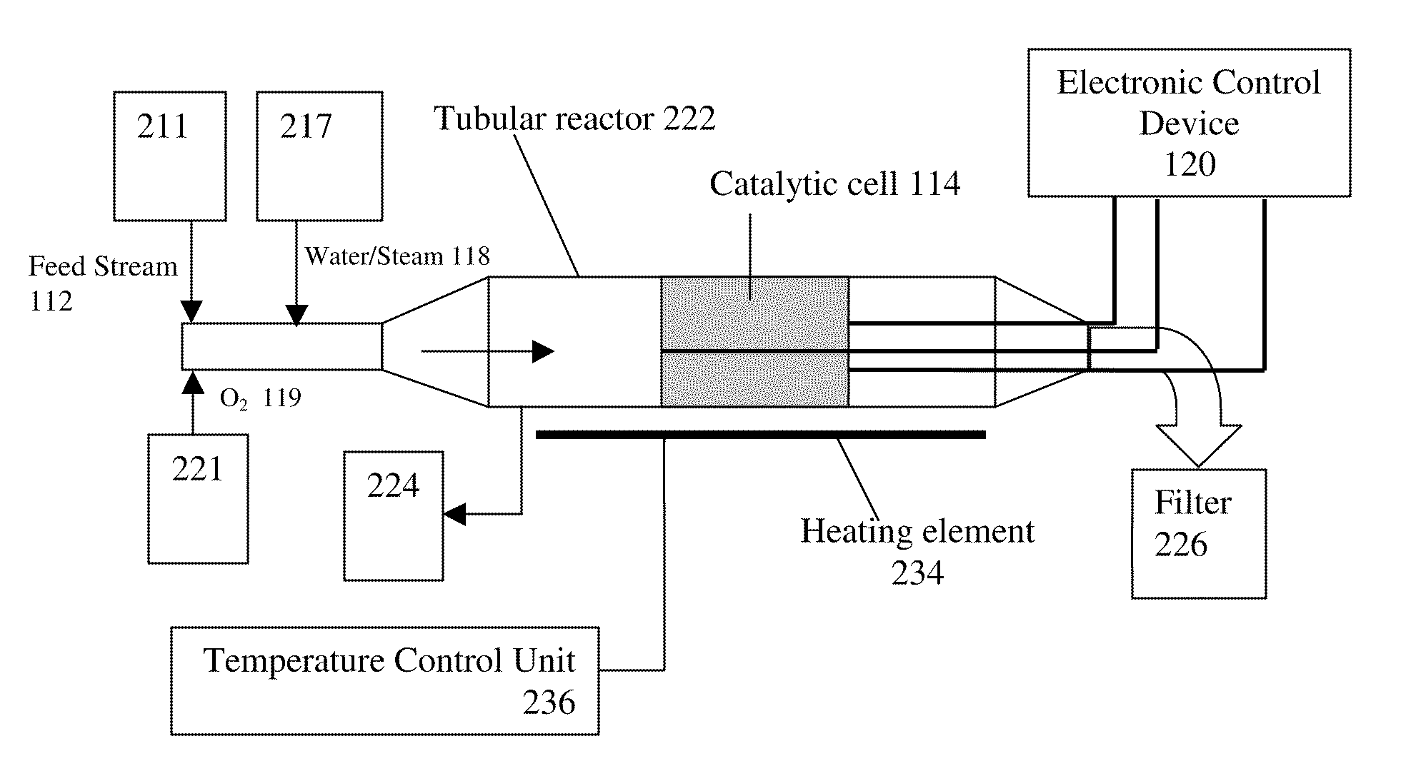
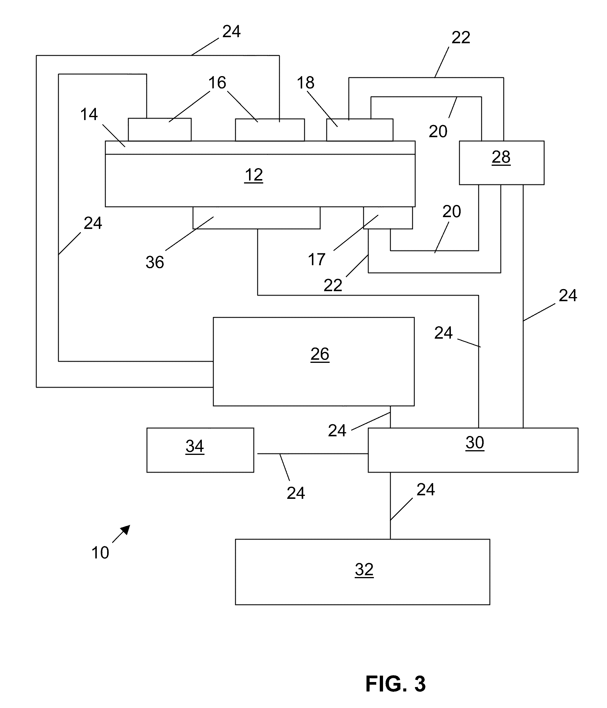
It describes a method and apparatus for controlling a process for depositing carbon particles onto a catalyst layer using an asymmetrical alternating current. By monitoring the impedance of the catalyst layer, the amount of carbon particles deposited can be controlled. This allows for control over the structure and amount of carbon particles. The method also involves applying a carrier gas containing oxygen and controlling the partial pressure of oxygen to enhance the deposition of carbon particles. The amount of heat applied to the catalyst layer can also be controlled to further control the structure and thickness of the deposited carbon particles. This technology is useful in the production of carbon-based materials for various applications.

Problems solved by technology

A problem encountered with prior art catalyst systems is poisoning of the catalyst.
Carbon monoxide interferes with the catalysis mechanism.
Another source of poisoning is the deposition of carbon.
However, the enhancement of the catalytic activity achieved by the NEMCA effect is very difficult to control.
One problem encountered with application of a DC electric field to catalyst systems is a lack of a means for monitoring and sensing the level of poisoning present in the catalyst in real time or on a continuous basis.
This lack of means to monitor and sense the level of poisoning in the catalyst in real time hinders precise and timely application of the DC electric fields.
The application of heat to catalyst systems also has the problem of a lack of real time control means, and also suffers from imprecise effects of temperature on catalyst behavior and the physical structure of the catalyst system.
If the temperature of the catalyst is too low, the catalyst may become fouled (dirty) and the kinetics of the catalyzed reaction may be negatively altered.
If the temperature is too high, the kinetics of the catalyzed reaction may be negatively altered and / or the microstructure of the catalyst may be destroyed.

Method used


Image

  • Methods for controlling catalytic processes, including the deposition of carbon based particles
  • Methods for controlling catalytic processes, including the deposition of carbon based particles
  • Methods for controlling catalytic processes, including the deposition of carbon based particles

Examples


Embodiment Construction

[0042]The ensuing detailed description provides exemplary embodiments only, and is not intended to limit the scope, applicability, or configuration of the invention. Rather, the ensuing detailed description of the exemplary embodiments will provide those skilled in the art with an enabling description for implementing an embodiment of the invention. It should be understood that various changes may be made in the function and arrangement of elements without departing from the spirit and scope of the invention as set forth in the appended claims.

[0043]Example embodiments of the present invention have been found to enhance the catalytic activity of prior art systems by a factor of 2 (and possibly more) as a consequence of the action of a process called the DECAN process (Dynamic Enhancement of the Catalytic Activity at Nanoscale), developed by Catelectric Corp., the assignee of the present invention.

[0044]Whereas the prior art NEMCA effect is essentially a DC phenomenon, the DECAN tech...


PUM

PropertyMeasurementUnit
phase angleaaaaaaaaaa
temperatureaaaaaaaaaa

Abstract

Methods and apparatus for controlling a catalytic layer deposition process are provided. A feed stream comprising a carbon source is provided to a catalyst layer. An asymmetrical alternating current is applied to the catalyst layer. A polarization impedance of the catalyst layer is monitored. The polarization impedance can be controlled by varying the asymmetrical alternating current. The controlling of the polarization impedance provides control over the structure and amount of carbon particles deposited on the catalyst layer. The carbon particles may be in the form of nanotubes, fullerenes, and / or nanoparticles.

Description

[0001]This application is a continuation-in-part of commonly-owned U.S. patent application Ser. No. 11 / 588,113 entitled “Methods and Apparatus for Controlling Catalytic Processes, Including Catalyst Regeneration and Soot Elimination” filed on Oct. 25, 2006, and also claims the benefit of U.S. provisional patent application No. 61 / 127,377 filed on May 12, 2008, each of which is incorporated herein and made a part hereof by reference for all purposes as if set forth in its entirety.[0002]U.S. patent application Ser. No. 11 / 588,113 is a continuation-in-part of commonly owned U.S. patent application Ser. No. 10 / 423,376 filed on Apr. 25, 2003 (now U.S. Pat. No. 7,325,392, issued on Feb. 5, 2008), and also claims the benefit of U.S. provisional patent application No. 60 / 731,570 filed on Oct. 28, 2005.BACKGROUND OF THE INVENTION[0003]The present invention relates generally to catalytic processes. More particularly, the present invention provides methods and apparatus for controlling a cata...

Claims


Application Information

Patent Timeline
Patent Type & Authority Patents(United States)
IPC IPC(8): C25B15/02C25D21/12D01F9/12
CPCB01D53/32B01D53/944C01B3/40C25B1/00C25B15/02H01M8/04395H01M8/04455H01M8/04552H01M8/04582H01M8/04641H01M8/04731H01M8/04902B01D2255/1021B01D2255/20715B01D2255/2092B01D2255/702B01D2258/012C01B2203/0233C01B2203/1082H01M2008/1095H01M2008/1293Y02E60/50Y02E60/525
Inventor STANCOVSKI, VICTOR
Owner CATELECTRIC
Learn More