Optical apparatus

a technology of optical apparatus and probe, which is applied in the direction of optical radiation measurement, instruments, spectrometry/spectrophotometry/monochromator, etc., can solve the problem that the probe of the linnmuir may not be suitable for use during the plasma process

Active Publication Date: 2013-04-09
IND ACADEMIC COOP FOUND YONSEI UNIV +1
View PDF6 Cites 18 Cited by
  • Summary
  • Abstract
  • Description
  • Claims
  • Application Information

AI Technical Summary

Problems solved by technology

For this reason, the Langmuir probe may not be suitable for use during a plasma process.

Method used


Image

  • Optical apparatus
  • Optical apparatus
  • Optical apparatus

Examples


Embodiment Construction

[0023]The present invention will now be described more fully hereinafter with reference to the accompanying drawings, in which preferred embodiments of the invention are shown. This invention, however, may be embodied in many different forms and should not be construed as limited to the embodiments set forth herein. In the drawings, the thicknesses of layers and regions are exaggerated for clarity. Like numbers refer to like elements throughout.

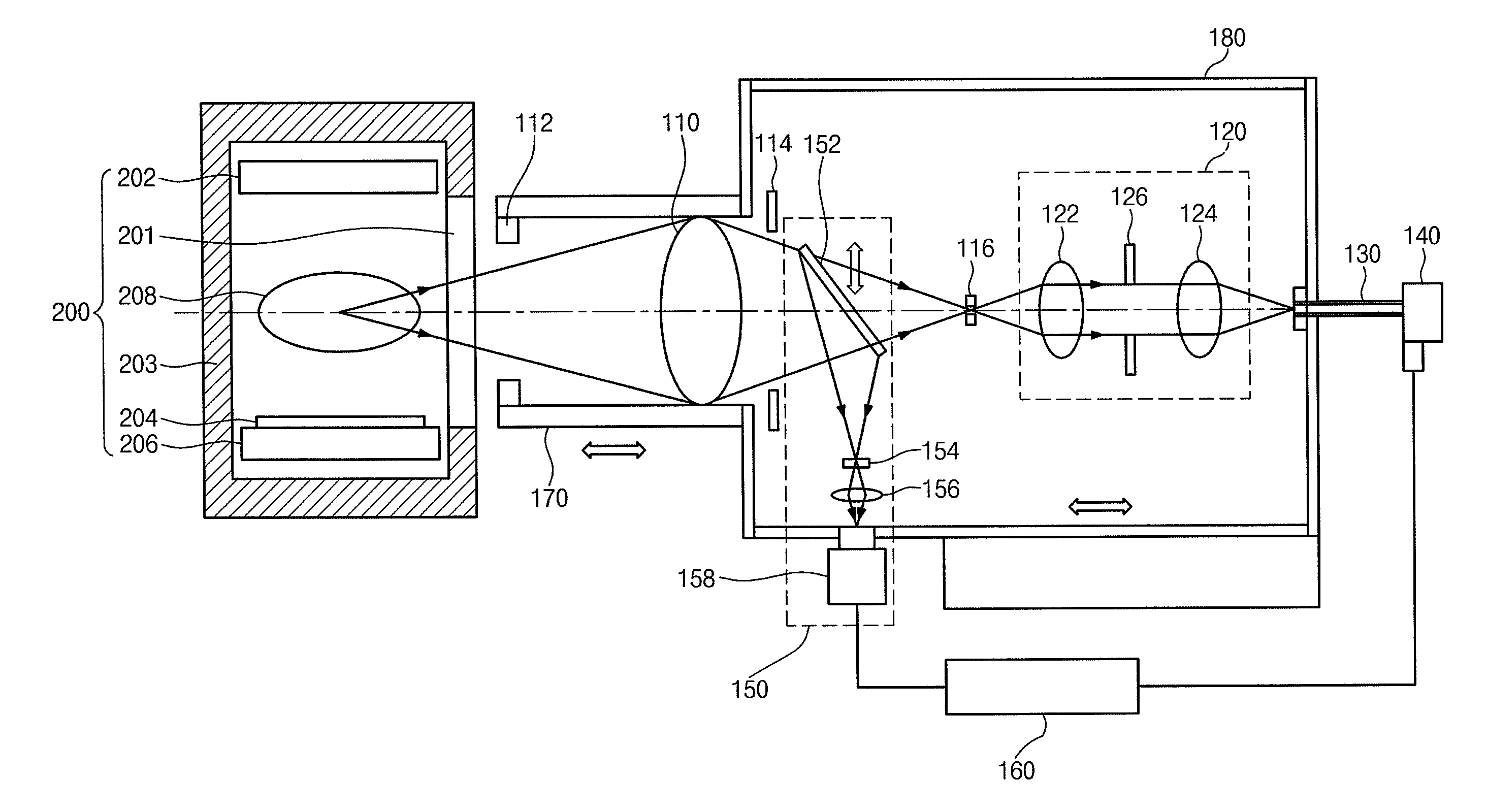
[0024]To obtain the desired process characteristics at a plasma generator, it may be necessary to know the plasma density and / or the radical density. The radical density may require measurement of spatial average as well as spatial distribution. As the critical dimension of semiconductor devices continues to shrink, it may become necessary to more minutely control a process distribution. Higher process uniformity may be required with the increase in diameter of wafers and the size of plasma generators.

[0025]When a process is not performed, pr...


PUM


Abstract

An optical apparatus for plasma includes a light collection lens provided to receive optical emission spectrum from plasma, a first aperture stop disposed between the light collection lens and the plasma to block out-focused light, a second aperture stop disposed between the light collection lens and an imaging area of the light collection lens to block in-focused light, and a pinhole disposed at the imaging area of the light collection lens to limit depth of focus.

Description

CROSS-REFERENCE TO RELATED APPLICATIONS[0001]This U.S. non-provisional patent application claims priority under 35 U.S.C. §119 to Korean Patent Application No. 10-2009-0010547, filed on Feb. 10, 2009, the disclosure of which is hereby incorporated by reference herein in it's entirety.BACKGROUND[0002]1. Technical Field[0003]The present disclosure relates to optical apparatuses and, more particularly, to an optical apparatus having a spatial resolution of light emitted from plasma.[0004]2. Description of Related Art[0005]A plasma process has been used in etching or deposition processes for semiconductors, flat-panel displays, solar cells, and so forth. The plasma process may be performed to supply chemical species such as, for example, radicals having high reactivity to a chemical reaction of a wafer or a substrate or to supply ions having kinetic energy. An etching or deposition process may be performed by the chemical species and / or the ions. In this case, predetermined process char...

Claims


Application Information

Patent Timeline
Patent Type & Authority Patents(United States)
IPC IPC(8): G02B9/00
CPCG01J3/02G01J3/0208G01J3/0229G01J3/0262G01J3/0289G01J3/443G02B21/0028H01L21/205H05H1/24
Inventor YI, HUNJUNGHAHN, JAE-WONCHAE, SEUNGKIOH, CHANG-HOON
Owner IND ACADEMIC COOP FOUND YONSEI UNIV
Why Eureka
Try Eureka