Frequency-scalable shockline-based VNA

a shockline and frequency-scalable technology, applied in the field of components, can solve the problems of increasing the noise figure of the sampler due to image-response conversion, providing equivalent-time sampling at the expense of increased conversion loss, and achieving optimal noise performance characteristics, reducing or increasing the fall time of the output voltage waveform, and achieving scalability and broadband performance.

Active Publication Date: 2013-04-09
ANRITSU CO
View PDF16 Cites 23 Cited by
  • Summary
  • Abstract
  • Description
  • Claims
  • Application Information

AI Technical Summary

Benefits of technology

[0023]Embodiments of the present invention provide a VNA system using NLTLs with frequency-scalable operation characteristics. To achieve scalability and broadband performance, multiple NLTL-based samplers are multiplexed together to form a single broadband reflectometer for a VNA. Each multiplexed NLTL-based sampler can then be configured to have optimal noise performance characteristics. Scaling to adjust noise performance vs. frequency for the reflectometer according to embodiments of the present invention is accomplished by: (1) increasing or decreasing the Bragg cutoff frequency of the shockline, such as by changing the spacing between varactor diodes of the NLTL, so as to either reduce or increase the fall time of its output voltage waveform; (2) changing the structure of the pulse forming network connected with the sampler, such as by changing the length of the voltage-step differentiator arms in the pulse forming network; and (3) changing the LO signal frequency applied to the shockline. These three methods together accomplish scaling while optimizing the tradeoff between conversion loss and bandwidth over a range of desired bandwidths.
[0024]To accomplish frequency scaling, a series of sampler-based NLTLs are provided along with multiplexing circuitry to allow selection of a desired NLTL assembly. The spacing between the varactor diodes in each NLTL is set differently in each shockline to allow user selection of the appropriate shockline assembly. Setting the spacing between varactor diodes and adjusting the length of the shorted stubs in the sampler circuitry allows scaling by shrinking or expanding the sampling pulse width. Finally, the VLO signal source can be provided through frequency multipliers to individual NLTL based sampler segments to provide desired LO signal ranges. Alternatively a crystal oscillator or other reference frequency source can be provided to synchronize different LO signal sources that supply each individual NLTL based sampler segment to provide selected LO signal ranges.
[0025]To accomplish multiplexing of the NLTL sampler segments so that different scaling can be used for each segment, one of several configurations can be used. In one configuration, each multiplexed NLTL segment includes a single NLTL integrated with a sampler or pulse forming network. The output of the pulse forming network is then used to gate two samplers. In another configuration, two separate NLTLs integrated with two separate pulse forming networks drive two separate test and reference samplers to provide better isolation between the test and reference channels.

Problems solved by technology

Equivalent-time sampling, however, is provided at the expense of increased conversion loss.
Commercial SRDs are traditionally limited to LO inputs having frequencies that do not exceed a few hundred MHz.
This limitation is a fundamental one in the context of microwave and millimeter-wave VNAs since it requires that a high harmonic number N be used in the down-conversion process, resulting in an increase in the noise figure of the sampler due to image-response conversion.
In addition, the use of a high harmonic number increases the number of spurious receiver responses and can reduce the effective dynamic range of a VNA.
Another fundamental limitation in an SRD-based VNA is the RF leakage between channels.
Thus with a purely passive network, there is an isolation limitation (signals leak from one sampler, through the distribution network, into another sampler).
But achieving frequencies above 65 GHz using SRDs has been prevented by the limited fall time for the SRD-based samplers.
For a step-like waveform, the trough of the wave travels at a faster phase velocity than the peak, resulting in compression of the fall time, and thus the formation of a steep wave front that approaches that of a shock wave.
These shockline implementations dealt with the generation of picosecond pulses for the purpose of gating samplers, making possible the down-conversion of extremely high frequency millimeter-wave and submillimeter-wave signals based on the use of lower harmonic numbers, and resulting in the concomitant improvement in noise figure and spurious responses.

Method used


Image

  • Frequency-scalable shockline-based VNA
  • Frequency-scalable shockline-based VNA
  • Frequency-scalable shockline-based VNA

Examples


Embodiment Construction

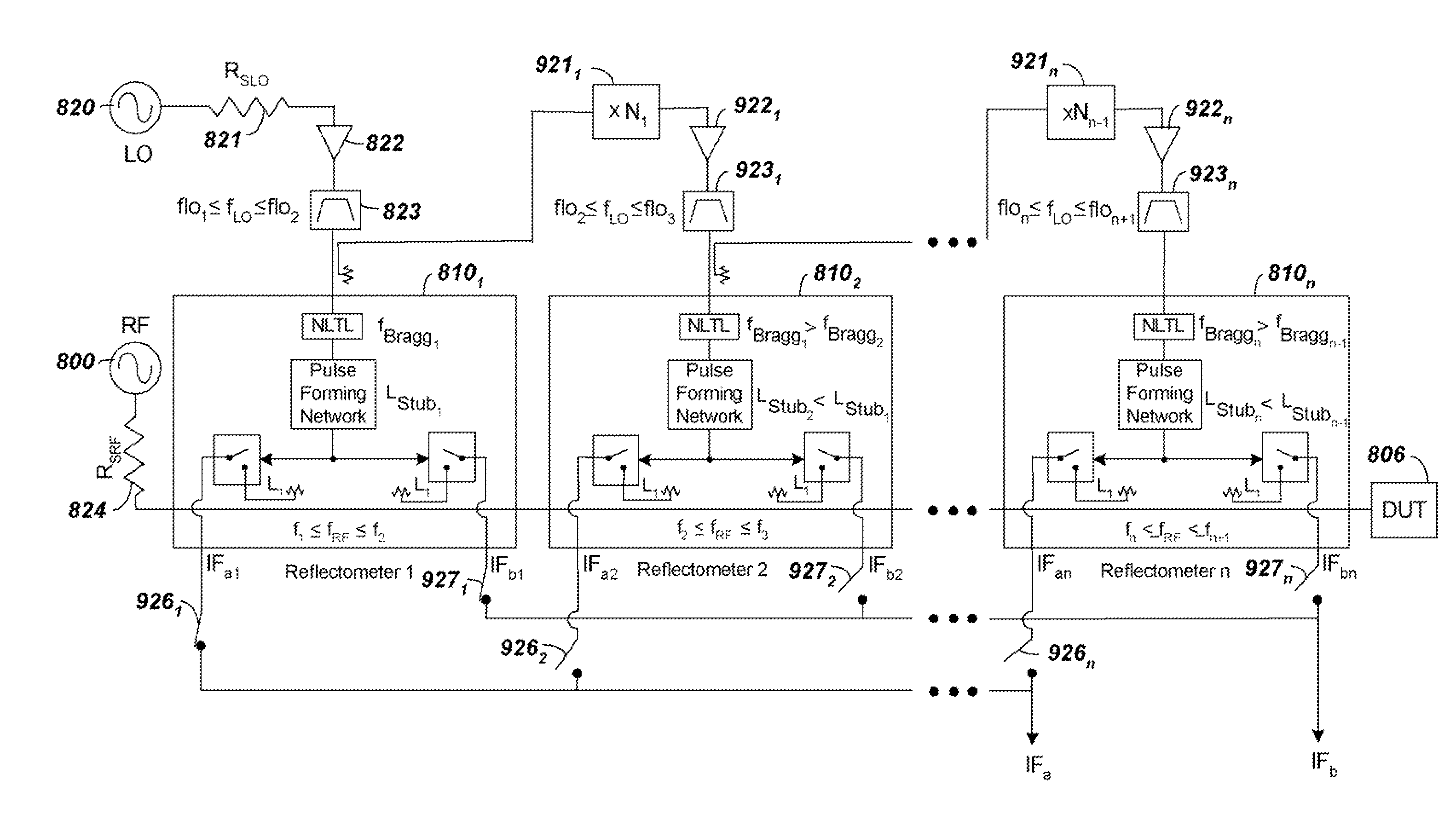
[0043]To accomplish frequency scaling when using NLTLs in embodiments of the present invention, it is initially realized that by changing gating time, Tg, frequency vs. conversion efficiency can be controlled. A reduction in the gating time Tg of the sampling Schottky diodes can be shown to provide an increase in RF output bandwidth at the expense of reduced conversion efficiency. Adjusting the Bragg frequency of the NLTL as well as the length of the shorted stubs in the sampler changes this gating time, Tg, and thus allows scaling of the sampler's RF bandwidth.

[0044]FIG. 6 shows a time-domain illustration of a harmonic sampling process wherein an ideal switch gated by a VLO signal at a rate 1 / TLO samples an RF signal VRF with a gating time of Tg to produce an output VIF. The plots of FIG. 6 illustrate the effect of adjusting gating time Tg in the switch with the realization that the periodic nature of the RF waves makes possible their down-conversion by equivalent-time sampling, al...


PUM


Abstract

A high-frequency VNA system is provided using non-linear transmission line (NLTL or shockline) based samplers configured to provide scalable operation characteristics. Scaling to adjust noise performance vs. frequency is accomplished as follows: (1) increasing or decreasing the fall time of a shockline's output voltage waveform. This is accomplished by changing the number of Schottky varactors in a shockline, as well as changing the shockline's Bragg cutoff frequency by setting the spacing between Schottky varactors; (2) changing the structure of the pulse-forming network connected with the sampler by changing the length of the differentiator arms in the sampler pulse-forming network; and (3) changing the LO signal frequency applied to the shockline. Multiple NLTL based samplers are multiplexed to form a broadband reflectometer with the multiplexing circuitry selectively connecting one of the NLTL based sampler segments at a time to allow user selection of a desired performance vs. frequency response for each segment.

Description

BACKGROUND[0001]1. Technical Field[0002]The present invention relates to components that extend the frequency range of a Vector Network Analyzer (VNA). More particularly, the present invention relates to high-frequency components such as non-linear transmission lines or shocklines that enable sampler-based VNAs to operate at high frequencies.[0003]2. Related ArtA. High-Frequency Sampler-Based VNA Receivers in General[0004]Sampler-based VNA receivers make use of equivalent-time sampling to down-convert RF stimulus and response signals to lower intermediate-frequency (IF) signals. In effect, the samplers “time-stretch” coupled versions of RF signal waves incident on and reflected from a device under test (DUT). This sampling approach results in a simplified VNA architecture with reduced cost in comparison with one employing fundamental mixing where the RF-to-IF conversion is made using the fundamental local oscillator (LO) signal as opposed to a harmonic of the LO.[0005]FIG. 1 shows a...

Claims


Application Information

Patent Timeline
Patent Type & Authority Patents(United States)
IPC IPC(8): H04B17/00G01R19/00
CPCG01R31/2841G01R27/32
Inventor NOUJEIM, KARAM MICHAELMARTENS, JON S.
Owner ANRITSU CO
Why Eureka
Try Eureka