Upconverter

a technology of upconverter and output converter, applied in the field of upconverter, can solve the problems of increasing structure cost and inconvenience, wireless implementations giving rise to new problems, and downtime between scans, so as to reduce the gain required, improve the self-powered parametric amplifier, and reduce noise.

Active Publication Date: 2013-04-16
SIEMENS HEALTHCARE GMBH
View PDF26 Cites 2 Cited by
  • Summary
  • Abstract
  • Description
  • Claims
  • Application Information

AI Technical Summary

Benefits of technology

[0008]The self powered parametric amplifier is improved by the addition of the, low noise amplifier. The local oscillator signal received at the antenna provides a source of power for both the parametric amplifier and the low noise amplifier. The low noise amplifier reduces the gain required in the parametric amplifier, improving stability and also provides isolation between a local coil from which an input is received, reducing variations in RF impedance seen by the parametric amplifier at the first port.

Problems solved by technology

These add cost and inconvenience to the structure.
In use, the requirement to connect the cables and sterilize them between scanning one patient and the next leads to down-time between scans.
However, wireless implementations give rise to new problems.

Method used


Image

  • Upconverter
  • Upconverter
  • Upconverter

Examples


Embodiment Construction

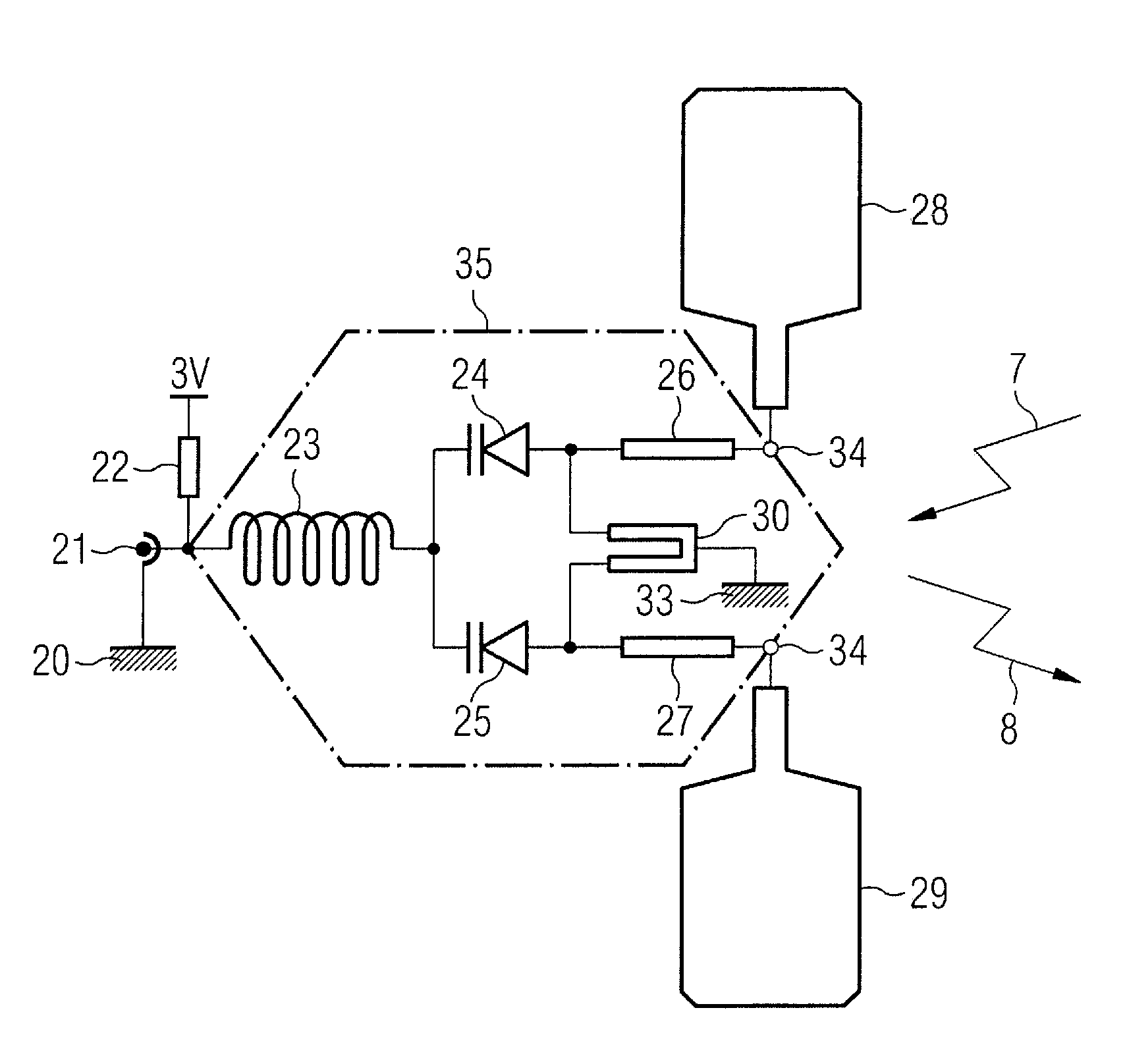
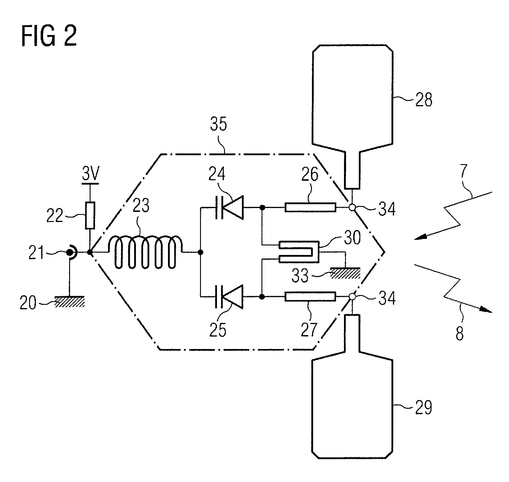
[0025]The wireless concept to which the features of the present invention apply is based on upconversion, in the patient mat, of the RF (Larmor) frequency signals from the patient coils to microwave frequencies for transmission to microwave antennas located on the bore of the scanner. The combination of transmit and receive antennas on the patient and bore respectively constitutes a MIMO (Multiple Input / Multiple Output) system. The greater multiplicity of receive antennas in the bore array allows individual signals from a number of patient antennas to be resolved. The present invention relates to an implementation of the upconversion process.

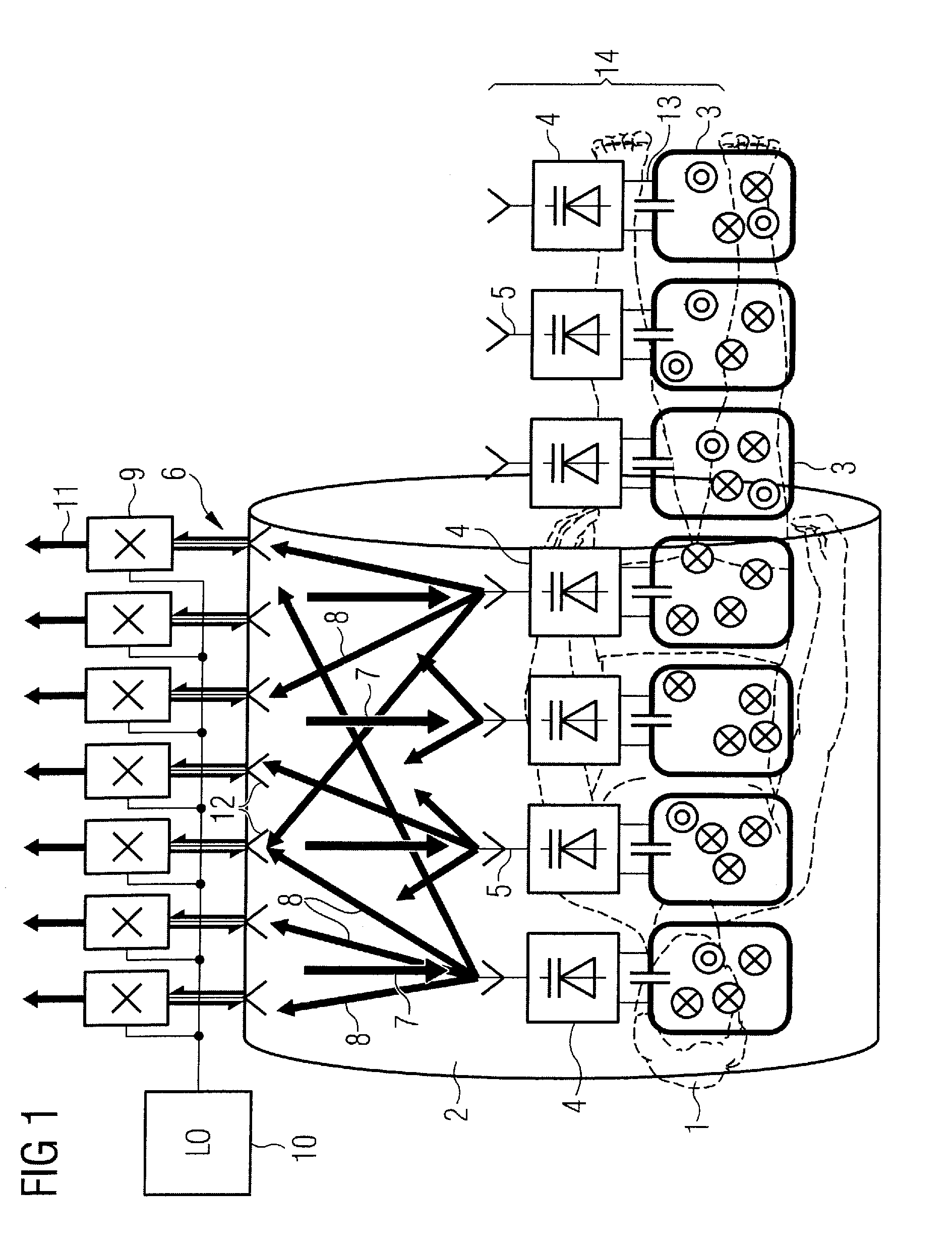
[0026]An example of an MRI system using a MIMO microwave link, in which amplifiers in accordance with the present invention are used, will now be described. FIG. 1 shows a patient 1 within an MRI scanner bore tube 2. A mat covers the part of the patient for imaging and embedded in the mat are a number of local coils 3. Associated with each local...


PUM


Abstract

An upconverter has a two port parametric amplifier that has a first port to receive an input signal to be amplified and upconverted and a second port to receive a local oscillator signal and to output the amplified, upconverted signal at upper and lower sideband frequencies. The upconverter further has an antenna coupled to the second port to receive the local oscillator signal and transmit the amplified, upconverted signal at upper and lower sideband frequencies and a low noise amplifier at the first port of the parametric amplifier, which is powered by the local oscillator signal.

Description

BACKGROUND OF THE INVENTION[0001]1. Field of the Invention[0002]This invention relates to an upconverter using a two port parametric amplifier, in particular for use in magnetic resonance imaging (MRI) systems.[0003]2. Description of the Prior Art and Related Subject Matter[0004]MRI scanners use a combination of a strong constant magnetic field (B0) from a superconducting magnet that is modified by gradient fields generated by gradient coils, together with a rotating magnetic field (B1) from a radio frequency (RF) antenna to excite nuclear magnetic resonances in the body that generate short term RF signals that are received to build up a tomographic image.[0005]All current-generation MRI scanners employ arrays of local coils mounted in close proximity to the scanned patient to receive the RF with maximum possible signal to noise ratio (SNR). The local coils that receive signals from the back of the patient are mounted in the patient table. Local coils that receive signals from the f...

Claims


Application Information

Patent Timeline
Patent Type & Authority Patents(United States)
IPC IPC(8): G01V3/00G01R33/20
CPCG01R33/3415G01R33/3621G01R33/3692H03F7/04G01R33/36
Inventor HULBERT, ANTHONY PETER
Owner SIEMENS HEALTHCARE GMBH
Why Eureka
Try Eureka