Oil-degradation detecting apparatus

a detection apparatus and oil technology, applied in the direction of resistance/reactance/impedence, measurement devices, instruments, etc., can solve the problems of limiting the accuracy of oil degradation judgment by measuring a single piece of information, affecting the electrical resistance value, etc., to achieve the effect of avoiding unnecessary oil change work and allowing more accurate judgment of oil degradation

Active Publication Date: 2013-04-16
MITSUBISHI HEAVY IND LTD
View PDF25 Cites 11 Cited by
  • Summary
  • Abstract
  • Description
  • Claims
  • Application Information

AI Technical Summary

Benefits of technology

[0008]The present invention has been accomplished for solving the above-mentioned problems, and it is an object thereof to provide an oil-degradation detecting apparatus that can more accurately judge degradation of oil and a mechanical system having a rotating part or a sliding part and including the oil-degradation detecting apparatus.
[0029]According to the present invention, since the degradation of oil can be judged based on the electrical conductivity and the dielectric constant, electrical characteristics associated with degradation of the oil or intrusion of a contaminant can be ascertained two-dimensionally from the viewpoints of the electrical conductivity and the dielectric constant. Therefore, an advantage is afforded in that the degradation of the oil can be more adequately judged.

Problems solved by technology

However, in the method disclosed in the above-described Patent Document 1, the degradation of oil is judged based on a change in the electrical resistance value, and therefore there are situations where the method is too sensitive to intrusion of materials that highly affect the electrical resistance value, such as intrusion of carbon (soot).
These methods all have advantages and disadvantages, and there are situations where there is a limit to accurate judgment of oil degradation by measuring a single piece of information.

Method used


Image

  • Oil-degradation detecting apparatus
  • Oil-degradation detecting apparatus
  • Oil-degradation detecting apparatus

Examples


modification 1

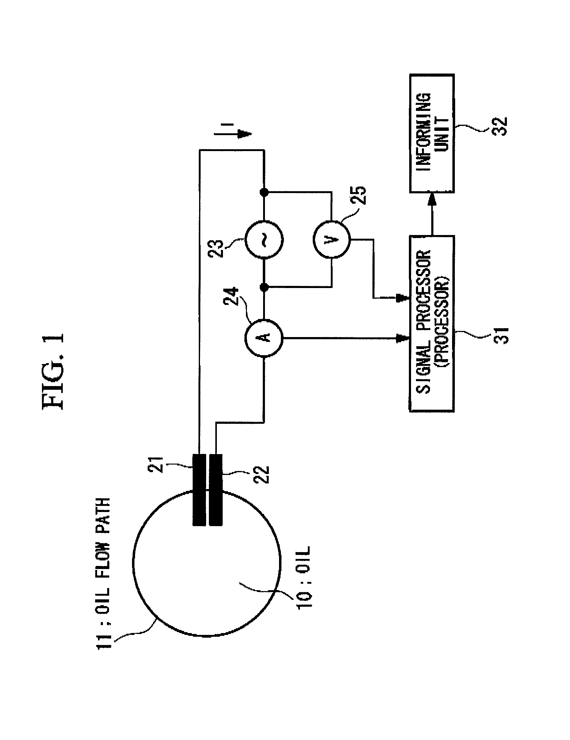
[0080]For example, a viscometer (viscosity sensor) for measuring the viscosity of the oil 10 may be further provided in the oil flow path 11, and the signal processor (processor) 31 may judge the degradation of the oil 10 by additionally using the measurement result from the viscometer (viscosity sensor).

[0081]In the above-described Embodiment, the degradation of the oil 10 is judged based on the electrical characteristics, i.e., the electrical conductivity and the dielectric constant ∈, of the oil 10, and there is difficulty in determining intrusion of a material (for example, fuel in the case where the oil-degradation detecting apparatus is applied to an internal-combustion engine) having similar electrical characteristics to those of the oil 10. Accordingly, as in Modification 1, it becomes possible to compensate for a decrease in the viscosity due to, for example, intrusion of fuel (judge degradation of the oil 10 and inform it) by adding viscosity to the judgment parameters of ...

modification 2

[0082]For example, a moisture meter for measuring the moisture of the oil 10 may be further provided in the oil flow path 11, and the signal processor (processor) 31 may judge the degradation of the oil 10 by additionally using the measurement result from the moisture meter.

[0083]Changes in the electrical characteristics (electrical conductivity and dielectric constant) of the oil 10 are typically caused by intrusion of water, thermal degradation, or intrusion of soot, but when a change in the electrical characteristics (electrical conductivity and dielectric constant) is small, there is difficulty in determining which is the cause. Accordingly, as in Modification 2, it becomes possible to determine which is the cause of the change in the electrical characteristics (electrical conductivity and dielectric constant) by adding moisture to the judgment parameters of the degradation judgment of the oil 10. That is, the degradation of the oil 10 can be judged multidimensionally based on t...

modification 3

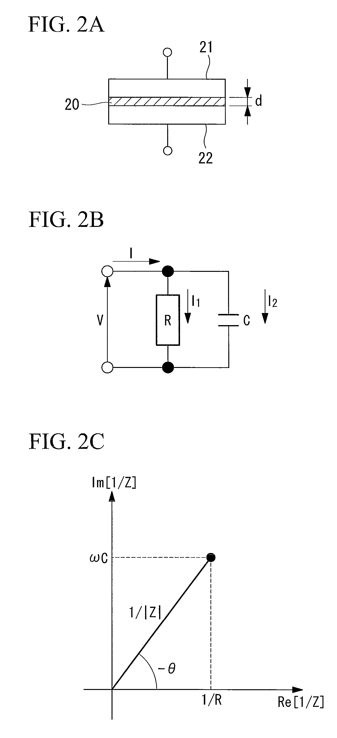
[0084]In addition, in the above-mentioned Embodiment, a sine wave is used as the waveform of the AC voltage, but a square wave, a triangle wave, a sawtooth wave, or a reverse sawtooth wave may be used. In such a case, harmonic components that are the integral multiple of the fundamental frequency can be obtained by Fourier transformation of the time function of the resulting impedance, and the electrical conductivities and the dielectric constants for a plurality of frequencies can be obtained simultaneously by determining the electrical conductivity and the dielectric constant of each harmonic component. That is, in the Embodiment, in order to increase the sensitivity, a plurality of frequencies is used as samples, and a more appropriate frequency is selected for measurement. However, information of a plurality of frequencies can be obtained by using a square wave, a triangle wave, a sawtooth wave, or a reverse sawtooth wave, and thereby a more accurate frequency index can be obtai...


PUM

PropertyMeasurementUnit
dielectric constantaaaaaaaaaa

Abstract

An oil-degradation detecting apparatus that can more accurately judge oil degradation and a mechanical system having a rotating part or a sliding part and including the oil-degradation detecting apparatus are provided. Two plates (21, 22) are disposed in an oil flow path (11) so as to be parallel to each other, an ammeter (24) measures a current that flows when an AC voltage is applied between the two plates (21, 22), a voltmeter measures the voltage between the plates (21, 22), and a signal processor (processor) (31) determines the electrical conductivity and the dielectric constant of the oil (10) based on the measurement results from the ammeter (24) and the voltmeter (25) and judges degradation of the oil (10) based on the electrical conductivity and the dielectric constant.

Description

TECHNICAL FIELD[0001]The present invention relates to an oil-degradation detecting apparatus.BACKGROUND ART[0002]In general, a mechanical system having a rotating part and a sliding part includes an oil tank or an oil-supplying path for circulating and supplying oil to various components constituting the rotating or sliding part of the mechanical system or peripheral components thereof, and thereby smoothly operates each component while preventing them from becoming worn.[0003]The quality control of the oil in such a mechanical system is conventionally performed by chemical analysis, but chemical analysis takes a long time after oil sampling to give a result. Therefore, quality control cannot be done in a timely manner. Accordingly, there is a demand for developing an apparatus for detecting the state of oil degradation, and some have been proposed.[0004]For example, in the “engine-oil degradation detecting apparatus” disclosed in Japanese Unexamined Patent Application, Publication ...

Claims


Application Information

Patent Timeline
Patent Type & Authority Patents(United States)
IPC IPC(8): G01R27/08G01N11/00G01R27/26
CPCG01N33/2888G01N27/02G01N2011/0066
Inventor AKIYAMA, YOYANO, AKIHIKOKAGA, JUNICHIDEGUCHI, YOSHIHIROYAMAURA, TAKETOSHI
Owner MITSUBISHI HEAVY IND LTD
Why Eureka
Try Eureka