Annulus clamping and backside gas cooled electrostatic chuck

a technology of electrostatic chuck and annulus, which is applied in the field of electrostatic clamping and method of clamping workpieces, can solve the problems of affecting the efficiency of electrostatic clamping, so as to achieve the effect of further controlling the heat transfer coefficient within the volum

Active Publication Date: 2013-04-16
AXCELIS TECHNOLOGIES
View PDF25 Cites 32 Cited by
  • Summary
  • Abstract
  • Description
  • Claims
  • Application Information

AI Technical Summary

Benefits of technology

[0012]According to another exemplary aspect, a cooling plate associated with a backside of the clamping plate is further provided, wherein the cooling plate comprises one or more cooling channels configured to route a cooling fluid therethrough. In one example, the one or more cooling channels comprise a plurality of concentric channels interconnected via a plurality of radial passages. The plurality of concentric channels and plurality of radial passages, for example, are defined in a front surface of the cooling plate that faces a backside of the clamping plate. In another example, one or more radial channels are further defined along a backside surface of the cooling plate, wherein the backside surface of the cooling plate is generally opposite the front surface of the cooling plate. The configuration of the one or more cooling channels provides advantageous cooling to the clamping plate, while generally preventing bubble formation therein.

Problems solved by technology

However, a charge transfer typically resulting from the use of a semiconductor dielectric, for example, can also transmit a charge to the wafer, therein generating residual clamping forces that can result in a delay in releasing the wafer from the clamp.
The resulting electrode structures can be quite complicated because of the design constraints driven by the need to maximize clamping area and force.
However, increasing the clamping force on the entire workpiece can have deleterious effects, such as increased particulate contamination, since the increased clamping pressure can cause frictional forces between the ESC and the workpiece across the surface of the workpiece, thus leading to greater chances of particulate contamination across the areas of the workpiece in which devices are formed.
Thus, offsetting the clamping pressure with gas pressure, and vice versa, can be quite difficult in such a tightly coupled system.

Method used


Image

  • Annulus clamping and backside gas cooled electrostatic chuck
  • Annulus clamping and backside gas cooled electrostatic chuck
  • Annulus clamping and backside gas cooled electrostatic chuck

Examples


Embodiment Construction

[0024]The present invention is directed generally toward an electrostatic clamp or chuck (ESC) that provides improved clamping and thermal uniformity, while further decreasing backside particle contamination. Accordingly, the present invention will now be described with reference to the drawings, wherein like reference numerals may be used to refer to like elements throughout. It should be understood that the description of these aspects are merely illustrative and that they should not be interpreted in a limiting sense. In the following description, for purposes of explanation, numerous specific details are set forth in order to provide a thorough understanding of the present invention. It will be evident to one skilled in the art, however, that the present invention may be practiced without these specific details.

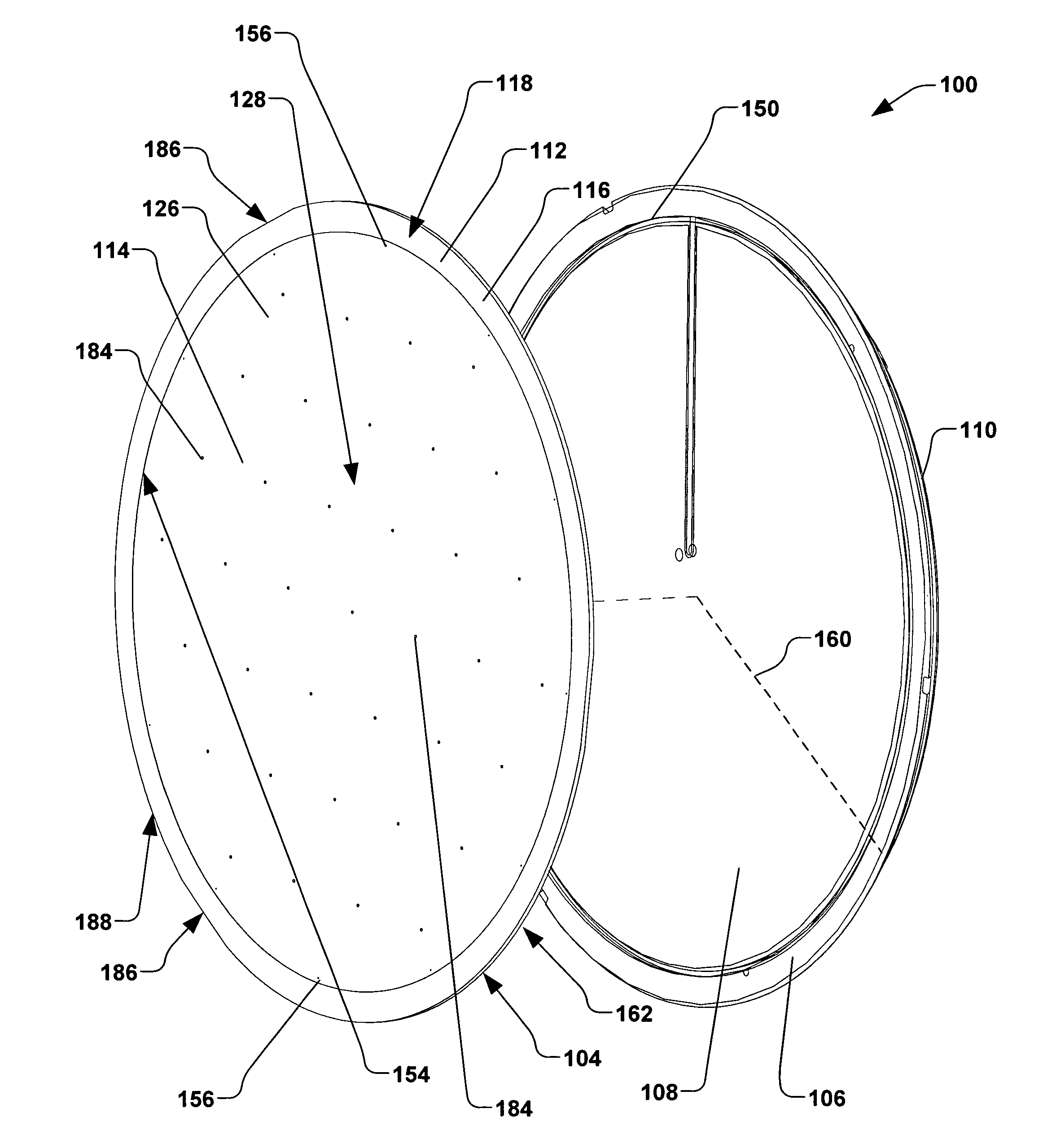
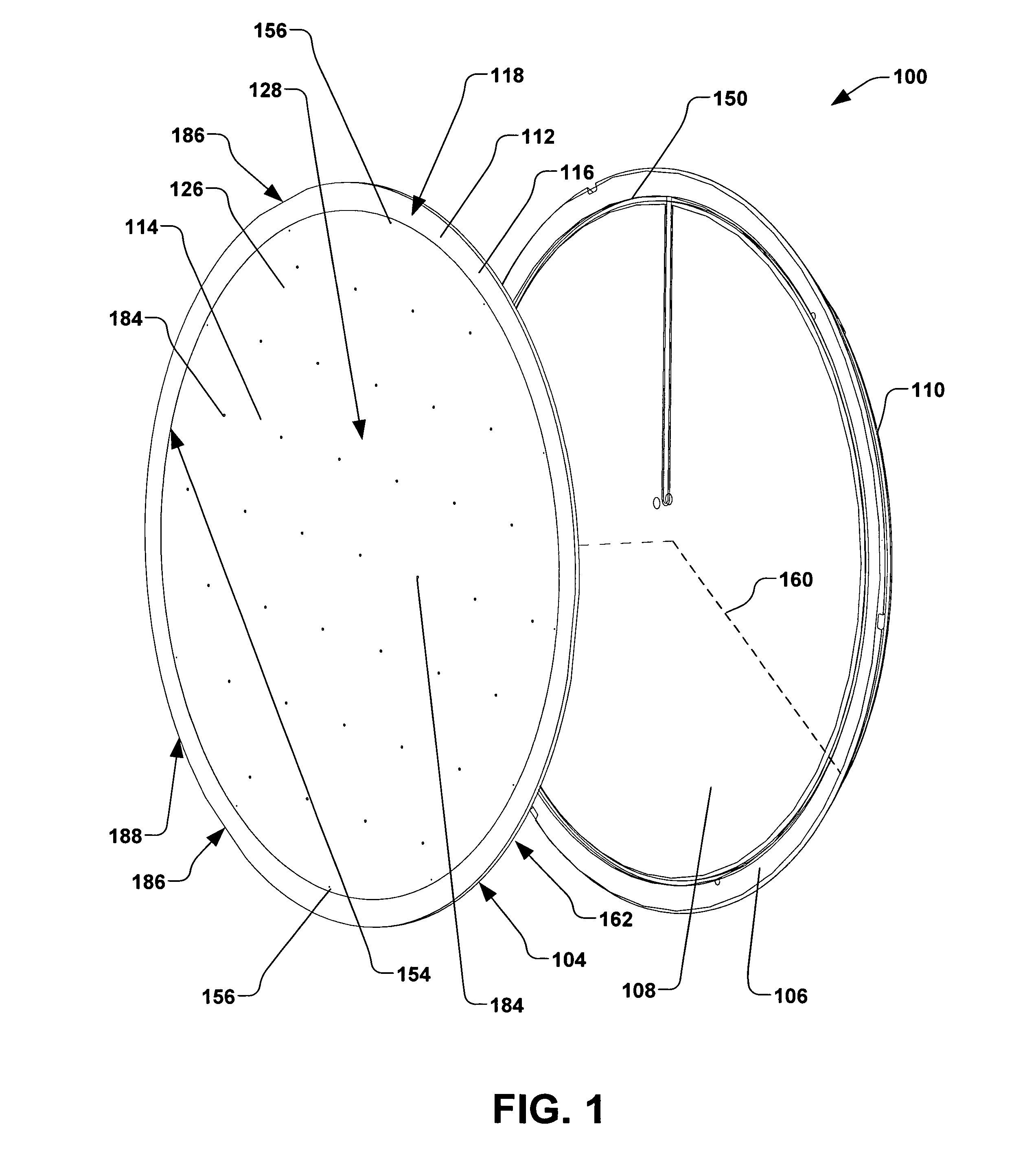
[0025]Referring now to the figures, FIG. 1 illustrates an exploded perspective view of an exemplary electrostatic clamp 100, also referred to as an “ESC”. The ESC 100 is ...


PUM


Abstract

An electrostatic clamp (ESC), system, and method for clamping a workpiece is provided. A clamping plate of the ESC has central disk and an annulus encircling the central disk, wherein the central disk is recessed from the annulus by a gap distance, therein defining a volume. Backside gas delivery apertures are positioned proximate to an interface between the annulus and the central disk. A first voltage to a first electrode of the annulus clamps a peripheral region of the workpiece to a first layer. A second voltage to a second electrode of the central disk generally compensates for a pressure of a backside gas within the volume. The ESC can be formed of J-R- or Coulombic-type materials. A cooling plate associated with the clamping plate further provides cooling by one or more cooling channels configured to route a cooling fluid therethrough.

Description

FIELD OF THE INVENTION[0001]The present invention relates generally to semiconductor processing clamping systems, and more specifically to an electrostatic clamp and method of clamping workpieces.BACKGROUND OF THE INVENTION[0002]Electrostatic clamps or chucks (ESCs) are often utilized in the semiconductor industry for clamping workpieces or substrates during plasma-based or vacuum-based semiconductor processes such as ion implantation, etching, chemical vapor deposition (CVD), etc. Clamping capabilities of the ESCs, as well as workpiece temperature control, have proven to be quite valuable in processing semiconductor substrates or wafers, such as silicon wafers. A typical ESC, for example, comprises a dielectric layer positioned over a conductive electrode, wherein the semiconductor wafer is placed on a surface of the ESC (e.g., the wafer is placed on a surface of the dielectric layer). During semiconductor processing (e.g., ion implantation), a clamping voltage is typically applied...

Claims


Application Information

Patent Timeline
Patent Type & Authority Patents(United States)
IPC IPC(8): H01L21/683
CPCH01L21/6833H01L21/683B23Q3/08H02N13/00
Inventor TAO, TENG CHAO D.LEE, WILLIAM D.LAFONTAINE, MARVIN R.PUROHIT, ASHWIN M.
Owner AXCELIS TECHNOLOGIES
Why Eureka
Try Eureka