Tunable-illumination reflector optics for UV cure system

Active Publication Date: 2013-04-23
NOVELLUS SYSTEMS
View PDF87 Cites 22 Cited by
  • Summary
  • Abstract
  • Description
  • Claims
  • Application Information

AI Technical Summary

Benefits of technology

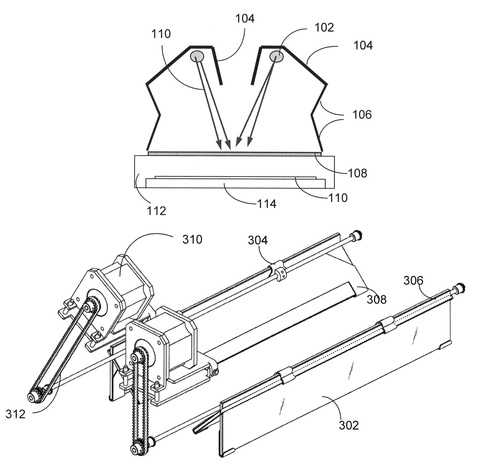
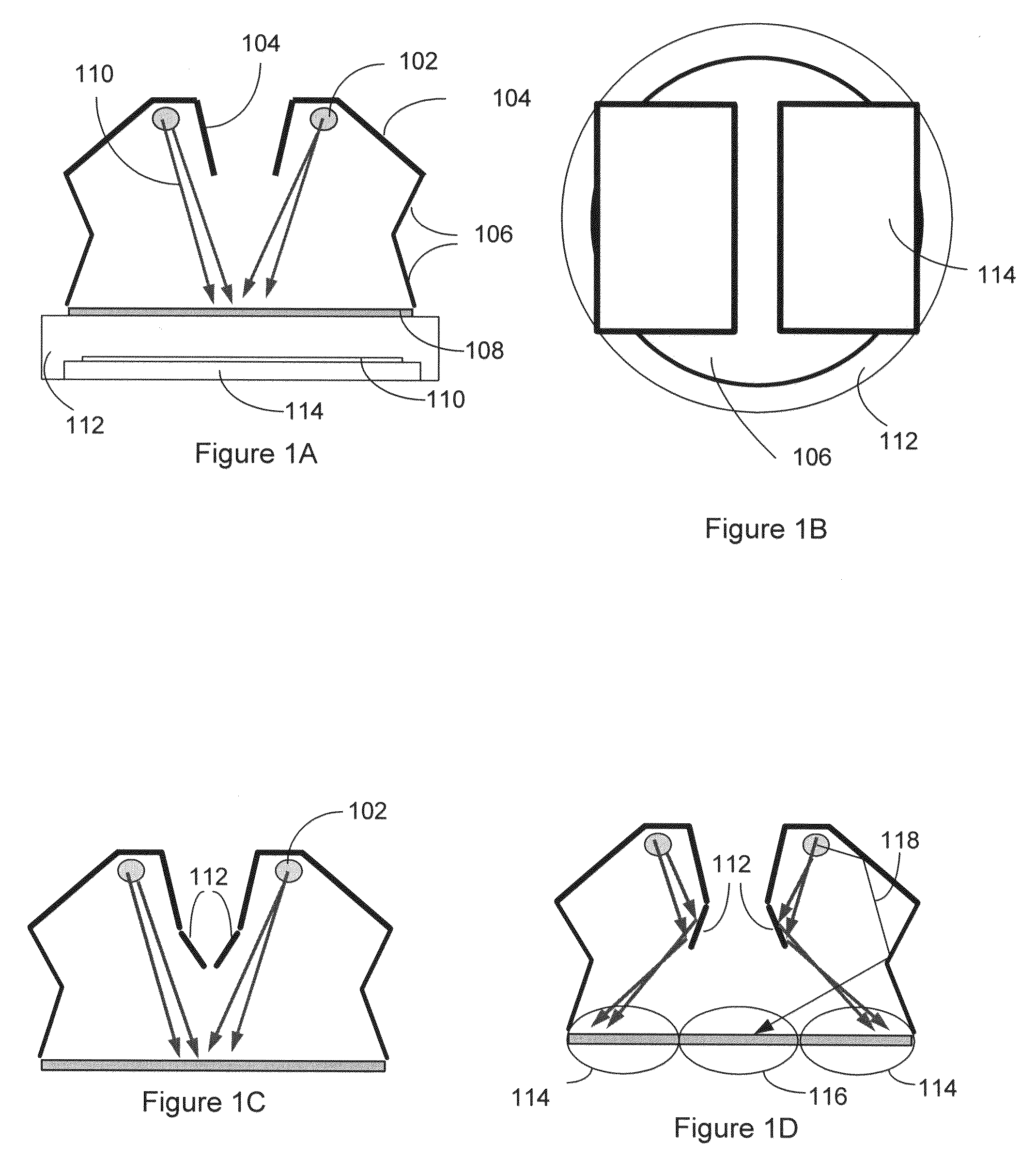
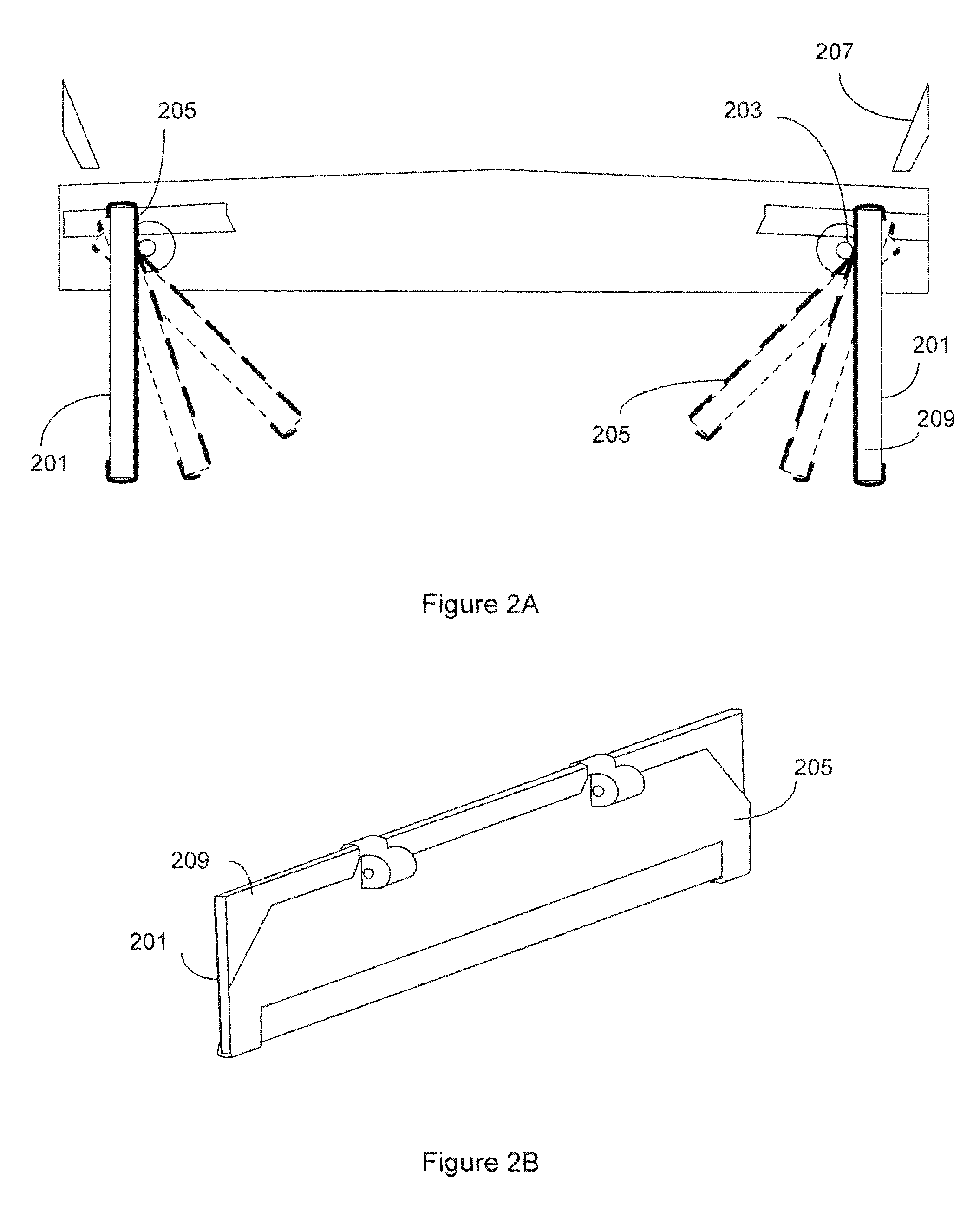
This patent discusses an improved apparatus and methods for using ultraviolet light to cure thin films. The invention includes a semiconductor processing apparatus with a UV lamp assembly and a central external reflector (CER). The CER is positioned outside of the chamber to not be affected by reactions that occur inside the chamber. By adjusting the angles of the optical reflectors, the CER can achieve different radiation profiles on the substrate. The substrate is exposed to reflected UV radiation from the CER and other reflectors as well as directly from the UV light source. The total exposure is a sum of all the various reflections and unreflected light and is a percentage of the light generated. This invention provides a larger percentage of the light generated as compared to other methods, which saves time, conserves power and parts.

Problems solved by technology

A thermal treatment may remove unwanted particles from the film, or change its stresses and other properties.
These thermal processes, however, have certain difficulties.
As is well known in the field, these conditions can damage copper containing devices, especially in the application wherein a low-k dielectric is being cured and the long exposure time may be unsuitable for mass manufacturing.
However, the use of UV radiation in such processes may result in deleterious side-effects unless special care is taken to deliver the precise amount of radiation and to maintain the substrate temperature at an optimal level.
Delivery of the precise amount of radiation may be complicated when the deposited film on the substrate is not perfectly uniform.

Method used


Image

  • Tunable-illumination reflector optics for UV cure system
  • Tunable-illumination reflector optics for UV cure system
  • Tunable-illumination reflector optics for UV cure system

Examples


Embodiment Construction

Introduction

[0029]In the following description, numerous specific details are set forth in order to provide a thorough understanding of the present invention. The present invention may be practiced without some or all of these specific details. In other instances, well known process operations have not been described in detail to not unnecessarily obscure the present invention. While the invention will be described in conjunction with the specific embodiments, it will be understood that it is not intended to limit the invention to the embodiments.

[0030]Reference will be made in detail to implementations of the present invention as illustrated in the accompanying drawings. The same reference indicators will be used throughout the drawings and the following detailed description to refer to the same or like parts. In this application, the terms “work piece,”“wafer” and “substrate” will be used interchangeably. The following detailed description assumes the invention is implemented on a...


PUM


Abstract

The present invention provides improved apparatus for ultraviolet (UV) cure of thin films. A central external reflector (CER) reflects UV light at different angles to compensate for non-uniformity of the deposited film on the substrate. The CER is positioned between the UV light source and the substrate and includes an actuator that can change the angle of reflection before and during UV cure.

Description

FIELD OF THE INVENTION[0001]This invention relates to apparatus and methods for radiation treatment of thin films.[0002]More specifically, the invention relates to apparatus and methods of using ultraviolet radiation and other process conditions to facilitate a desired change in film properties.BACKGROUND[0003]Many layers of thin films are used to make an integrated circuit. IC manufacturing requires thin films to have certain properties in order for the circuit to function as designed. For example, there is a general need for materials with low dielectric constants (low-k). Using low-k materials as the intermetal dielectric (i.e., the layer of insulator separating consecutive levels of the conductive metal interconnects) reduces the delay in signal propagation due to capacitive effects, otherwise know as the RC delay. A dielectric material of low dielectric constant will have low capacitance, and hence the RC delay of an IC constructed with such a material will be lower as well.[00...

Claims


Application Information

Patent Timeline
IPC IPC(8): F27B5/14F21V7/10F27B5/18F21V7/16
CPCB05D3/067H01L21/67115
Inventor BOLT, BRYAN
Owner NOVELLUS SYSTEMS
Why Eureka
Try Eureka