

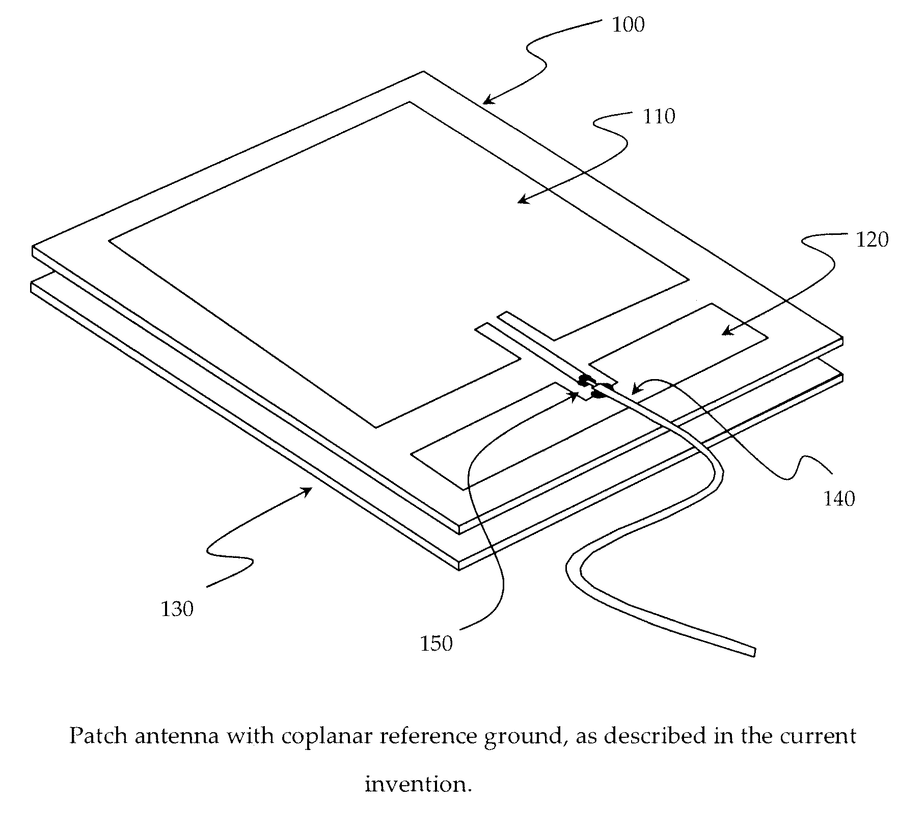
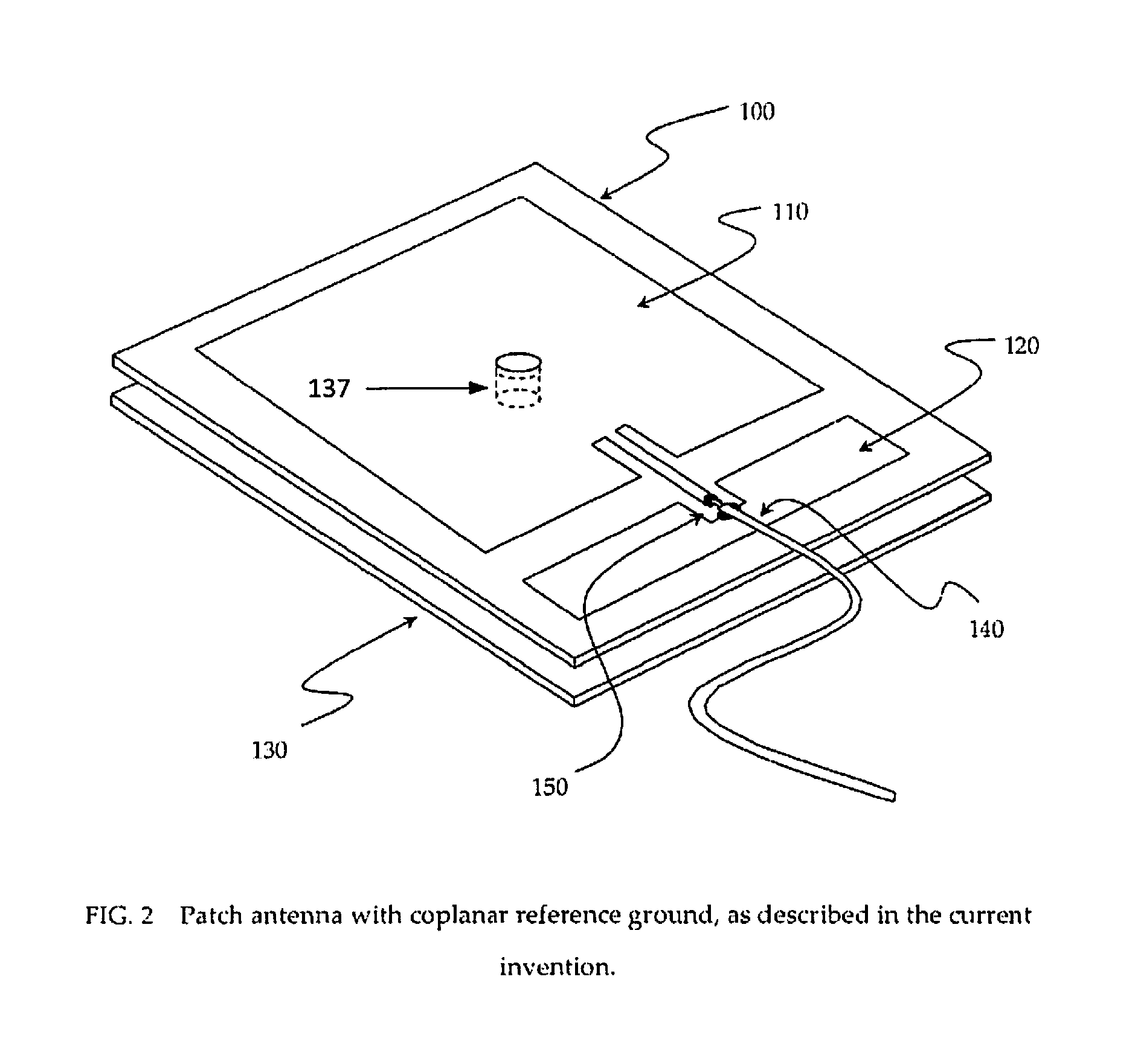
RFID patch antenna with coplanar reference ground and floating grounds
a coplanar reference ground and patch antenna technology, applied in waveguide type devices, substantially flat resonant elements, resonance antennas, etc., can solve the problems of poor performance of the overall rfid system and application failure, the design of the reader antenna becomes critical, and the situation is more complex and cannot be thought of as simply near-field or simply far-field, etc., to improve the electric or magnetic field strength or shape around the antenna. , control or optimize the effect of the electric or magneti
- Summary
- Abstract
- Description
- Claims
- Application Information
AI Technical Summary
Benefits of technology
Problems solved by technology
Method used
Image

Examples
Embodiment Construction
[0035]Preferred embodiments and applications of the current invention will now be described. Other embodiments may be realized and changes may be made to the disclosed embodiments without departing from the spirit or scope of the invention. Although the preferred embodiments disclosed herein have been particularly described as applied to the field of RFID systems, it should be readily apparent that the invention may be embodied in any technology having the same or similar problems.
[0036]In the following description, a reference is made to the accompanying drawings which form a part hereof and which illustrate several embodiments. It is understood that other embodiments may be utilized and structural and operational changes may be made without departing from the scope of the descriptions provided.
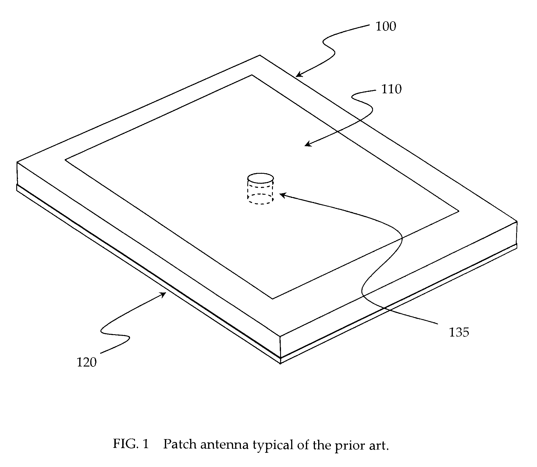
[0037]FIG. 1 is a drawing showing a patch antenna from the prior art. In this design the supporting dielectric material 100 separates the radiative antenna element 110 (top side of the diele...
PUM
| Property | Measurement | Unit |
|---|---|---|
| thickness | aaaaa | aaaaa |
| frequency | aaaaa | aaaaa |
| frequency | aaaaa | aaaaa |
Abstract
Description
Claims
Application Information