Driving method of semiconductor device
a driving method and semiconductor technology, applied in static storage, digital storage, instruments, etc., can solve the problems of negative shift to the threshold voltage, ease of discharge where charges are not sufficiently discharged, wrong data reading, etc., and achieve the effect of reducing the defect of wrong data reading
- Summary
- Abstract
- Description
- Claims
- Application Information
AI Technical Summary
Benefits of technology
Problems solved by technology
Method used
Image
Examples
embodiment 1
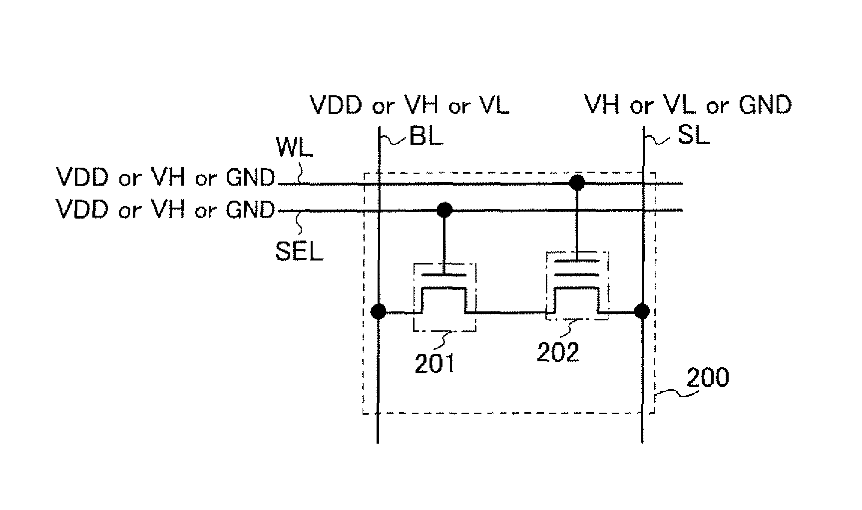
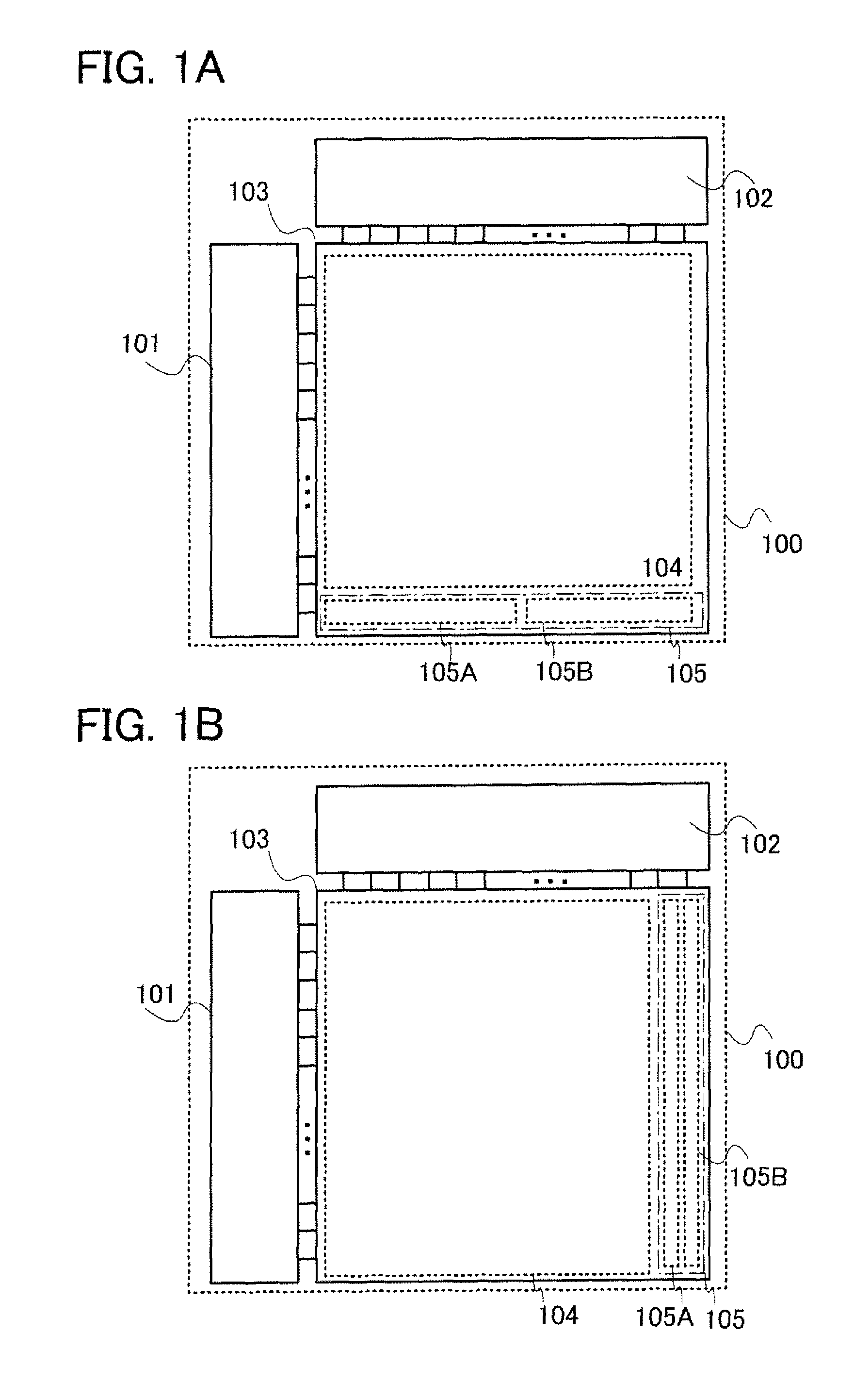
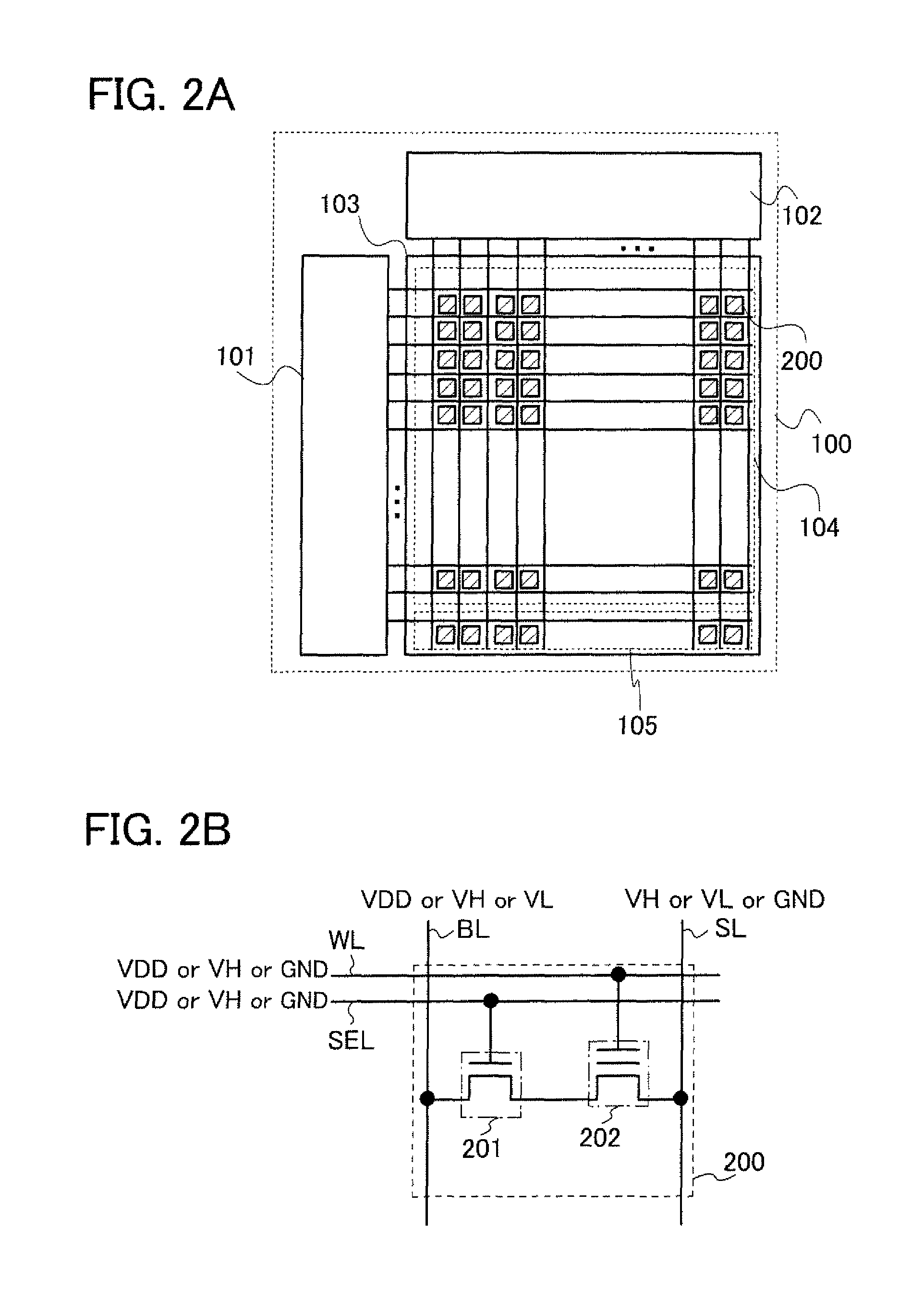
[0036]First, an example of a structure of a memory cell region (also referred to as a memory cell array) and a control circuit (also referred to as a driver circuit) which are included in a semiconductor device is illustrated in FIGS. 1A and 1B. A semiconductor device 100 in FIGS. 1A and 1B includes a row decoder 101, a column decoder 102, and a semiconductor memory circuit 103. The semiconductor memory circuit 103 includes a memory cell region 104 in which memory cells each including a non-volatile memory element are arranged in matrix, and a test region 105.
[0037]The test region 105 includes a first region 105A and a second region 105B. Note that FIG. 1A illustrates a structure in which the test region 105 is provided in parallel to the column decoder 102 such that the first region 105A and the second region 10513 in the test region 105 are controlled by one word line and selection line which are extended from the row decoder 101. That is, a memory cell is connected to the first r...
embodiment 2
[0082]In this embodiment, a structure of FIG. 1B will be described with reference to FIG. 8 and FIG. 9. Note that description which overlaps with Embodiment 1 is omitted and the description of Embodiment 1 is employed.
[0083]FIG. 8 specifically illustrates the memory cells in the memory cell region and the test region in FIG. 1B. The semiconductor device 100 illustrated in FIG. 8 includes the row decoder 101, the column decoder 102, and the semiconductor memory circuit 103 including the memory cell region 104 and the test region 105 as in FIG. 1B. The memory cell region 104 and the test region 105 include the memory cells 200 arranged in matrix. As an example, FIG. 8 illustrates a structure in which the memory cells 200 are arranged in a grid pattern.
[0084]Note that the description of the memory cell region 104, a structure of the memory cell 200, and a driving method of the semiconductor device 100 are the same as those in Embodiment 1.
[0085]Note that as illustrated in FIG. 9, the f...
embodiment 3
[0088]In this embodiment, a semiconductor memory device according to one embodiment of the present invention will be described.
[0089]An example of a structure of the semiconductor device described in the above embodiment is illustrated in FIG. 10.
[0090]In addition, FIG. 10 illustrates each signal input and output as well as a block diagram of the semiconductor device described in Embodiment 1. A semiconductor device 1000 illustrated in FIG. 10 includes an interface portion 1001, a boosting circuit 1002, the row decoder 101, the column decoder 102, and the semiconductor memory circuit 103.
[0091]Note that the semiconductor memory circuit 103 includes the memory cell region and the test region as in the above embodiment. To the interface portion 1001, address data (address) of the memory cell region and the test region in the semiconductor memory circuit 103, a writing control signal (WE), and a reading control signal (RE) are input from the outside of the semiconductor device 1000. Fu...
PUM
 Abstract
Description
Claims
Application Information
 - R&D
- Intellectual Property
- Life Sciences
- Materials
- Tech Scout
- Unparalleled Data Quality
- Higher Quality Content
- 60% Fewer Hallucinations
Browse by: Latest US Patents, China's latest patents, Technical Efficacy Thesaurus, Application Domain, Technology Topic, Popular Technical Reports.
© 2025 PatSnap. All rights reserved.Legal|Privacy policy|Modern Slavery Act Transparency Statement|Sitemap|About US| Contact US: help@patsnap.com


