Capturing images using a switchable imaging apparatus

a switchable imaging and image technology, applied in the field of image capture and display, can solve the problems of increasing optical design complexity and cost, affecting the natural appearance of the image, and the difficulty of compact device packaging, so as to achieve more natural image capture sessions and reduce the thickness dimension

Inactive Publication Date: 2013-05-21
MONUMENT PEAK VENTURES LLC
View PDF38 Cites 9 Cited by
  • Summary
  • Abstract
  • Description
  • Claims
  • Application Information

AI Technical Summary

Benefits of technology

[0022]This invention has the advantage that images are captured using a switchable imaging apparatus with a reduced thickness dimension. The switchable imaging apparatus provides for images of the viewer to be captured with direct eye-contact through the display.
[0023]It has the additional advantage that it allows the switchable imaging apparatus to be very nearly transparent during image capture, without making the camera components visible to the subject. This allows the person taking the image to use the display itself as the “viewfinder” for a more natural image capture session.

Problems solved by technology

Increased demand for more compact device packaging presents a particular challenge for DTS designs.
With conventional optical solutions for camera optics, there are trade-offs between size and thickness of the DTS device and image quality.
The optical path length can be severely constrained, increasing optical design complexity and cost.
Placing one or more cameras behind the display screen can add significant thickness and bulk and may be impractical for a hand-held device.
Positioning one or more cameras along edges of the display screen may alleviate some of the dimensional problems, but proves to be less satisfactory because the perspective of the camera is different from the perspective of a viewer who is observing the display.
In transparent displays, cameras in the display area obstruct the transparency of the display.
As such, the optical switches described are not suited for use in a transparent display because the light interacting with the display is not polarized and prisms would distort the transparent view through the transparent display.
The deflection provided by this optical switch, however, is slight, and is too small to be used in a transparent display.
Since these deflectors utilize prism elements, they would provide distorted views through transparent displays.
Although various configurations have been proposed for providing a DTS design, conventional solutions fall short of a solution that reduces the physical profile of the device, provides alignment between the perspective of the camera and the perspective of the display as observed by a viewer, and conceals or masks image capture components from visibility to the viewer who is also being imaged.

Method used


Image

  • Capturing images using a switchable imaging apparatus
  • Capturing images using a switchable imaging apparatus
  • Capturing images using a switchable imaging apparatus

Examples


example 1

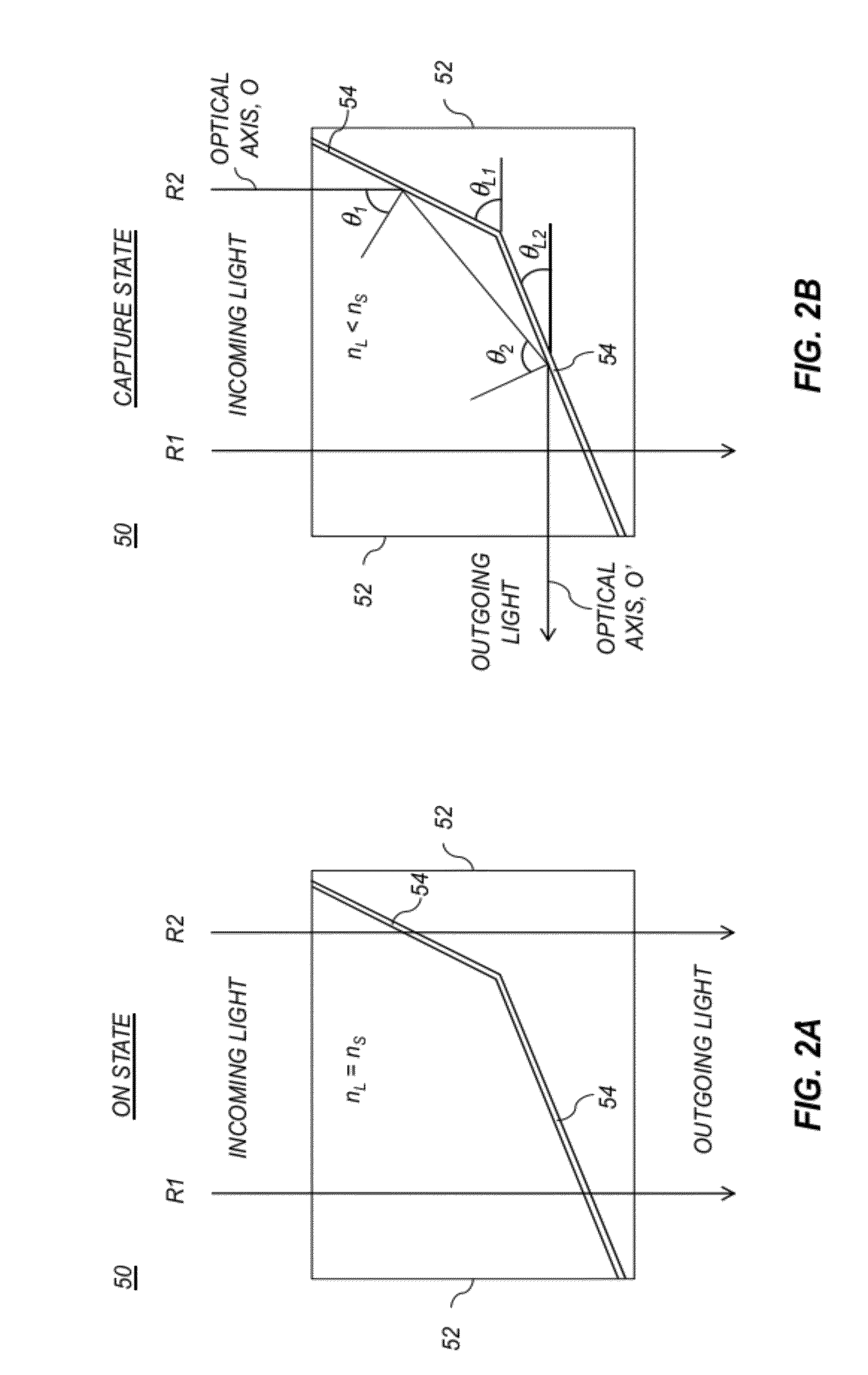
[0096]In a first exemplary embodiment, a switchable beam deflector 50 as shown in FIGS. 2A and 2B has two liquid crystal layers 54 made using liquid crystal material E63 from Merck. This liquid crystal material is switchable between refractive indices of nL,e=1.74 and nL,o=1.52 in response to an applied voltage signal. If the substrate 52 is fabricated with a material having a refractive index of nS=1.74, this provides a critical angle θc=60.9° when the refractive index of the liquid crystal material is at its lower value. The liquid crystal layers are positioned as shown in FIGS. 2A and 2B, with the layer nearer to the camera being oriented at an angle of θL2=22.5°, and the layer further from the camera being oriented at an angle of θL1=66.5°. With this arrangement, the light rays form consistent angles with the liquid crystal layers. The angle formed by the light rays and the normal to the surfaces of the liquid crystal layers of 67.5° is well above the critical angle θc=60.9° for...

example 2

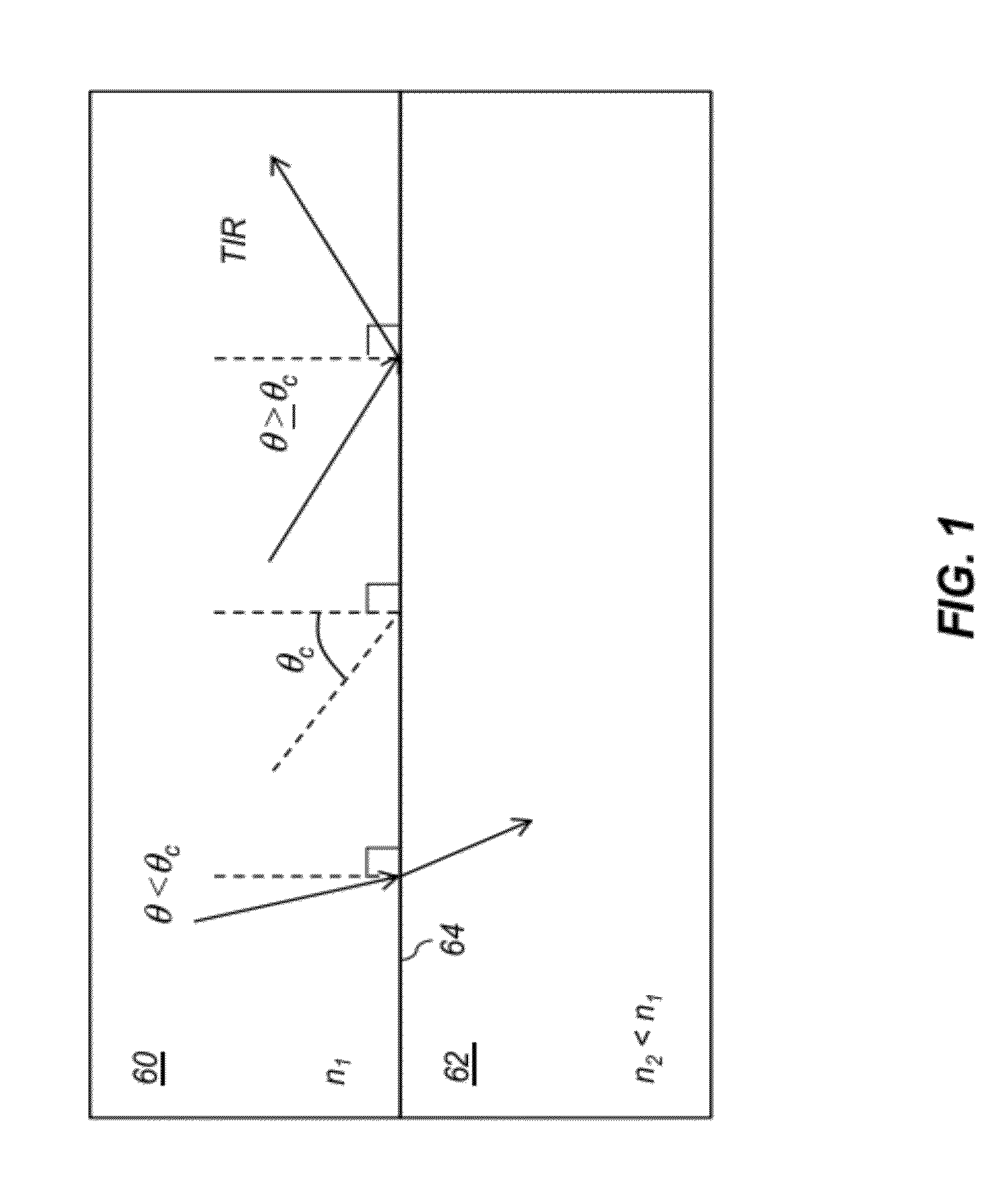
[0097]Similar to Example 1, using a liquid crystal material 18349 from Merck, which has refractive indices of nL,e=1.80 and nL,o=1.50. Assuming that the substrate 52 is fabricated with a material having a refractive index of nS=1.50, the critical angle θc=57.6, which is well below the angle formed by the light rays and the normal to the surfaces of the liquid crystal layers. Again, TIR conditions are provided.

example 3

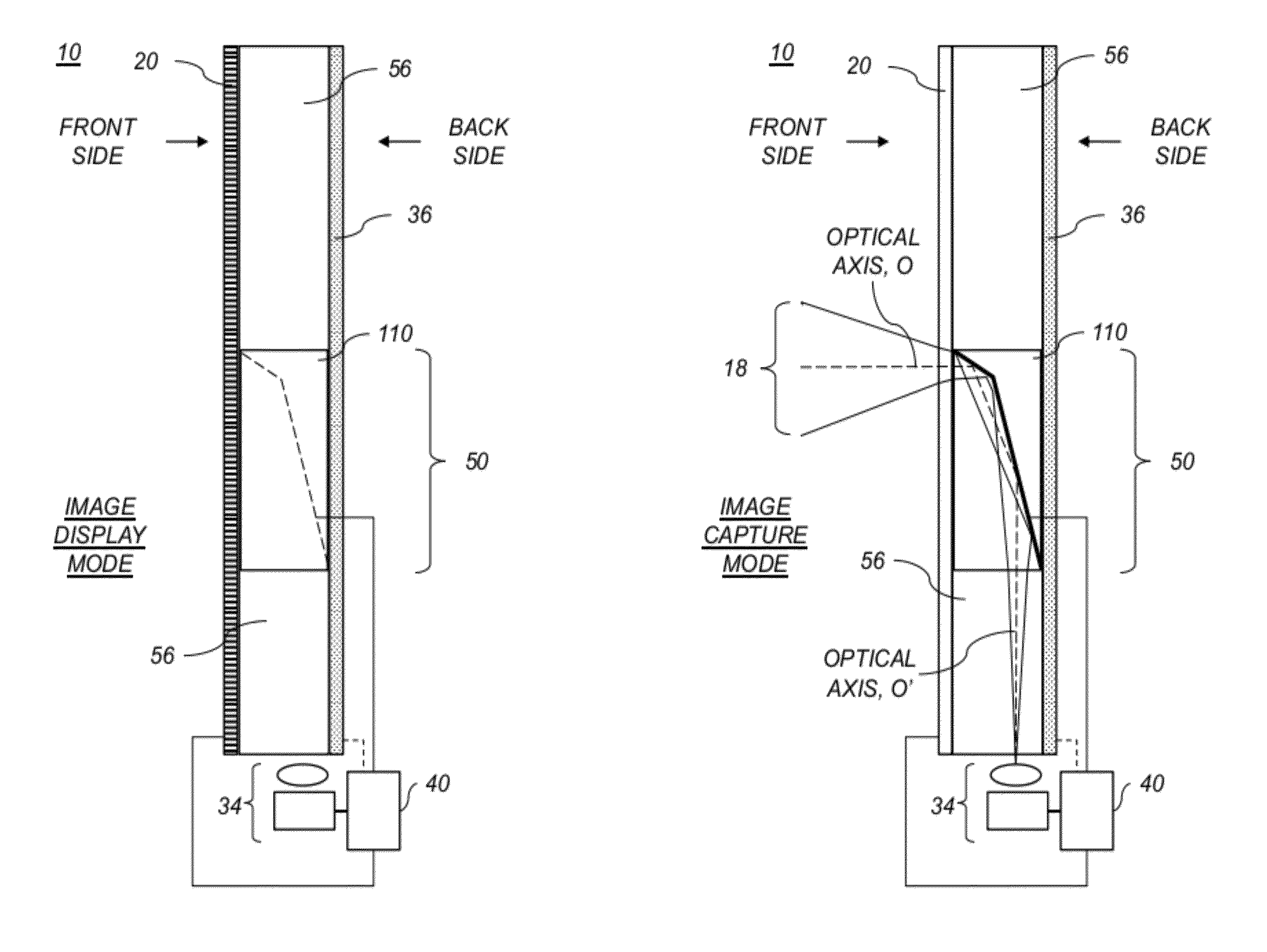
[0098]A transparent plate 110 similar to that shown in FIGS. 3A and 3B was designed. In this design, the transparent plate 110 was 50 mm high (top-to-bottom dimension in FIG. 3A) and 10 mm thick (left-to-right dimension in FIG. 3A), and was made from an optical material with a refractive index of 1.53. If the switchable imaging apparatus 120 has a 16:9 format, the width of the transparent plate 110 (out-of-page dimension in FIG. 3A) would be 89 mm. This would correspond to a 50 mm×90 mm display with a diagonal dimension of approximately 4 inches, which is comparable to display sizes used for consumer digital cameras. The optical path between the bottom edge of the transparent plate where the camera is located and the center of the switchable beam deflector 50 is then 25 mm. The switchable beam deflector aperture provided by the liquid crystal layer that is closer to the camera is then effectively 5 mm in the thickness direction and the full width of the switchable beam deflector in ...


PUM


Abstract

A method for capturing an image, comprising: providing a switchable imaging apparatus including a display screen having a first display state and a second transparent state, an optical beam deflector switchable between a first non-deflecting state and a second deflecting state, a camera positioned in a location peripheral to the display screen, and a controller; setting the switchable imaging apparatus to the image capture mode by using the controller to set the display screen to the second transparent state and the optical beam deflector to the second deflecting state; using the camera to capture an image of the scene; setting the switchable imaging apparatus to the image display mode by using the controller to set the display screen to the first display state and the optical beam deflector to the first non-deflecting state; and displaying an image on the display screen.

Description

CROSS-REFERENCE TO RELATED APPLICATIONS[0001]Reference is made to commonly assigned, co-pending U.S. Patent Application Publication No. 2012 / 0287320, entitled: “Switchable imaging apparatus for display and capture”, by Border et al.; to commonly assigned, co-pending U.S. Patent Application Publication No. 2012 / 0287326, entitled: “Switchable imaging apparatus for viewing and capture”, by Border et al.; to commonly assigned, co-pending U.S. Patent Application Publication No. 2012 / 0287323, entitled: “Imaging apparatus with switchable beam deflector array”, by Manico et al.; and to commonly assigned, co-pending U.S. Patent Application Publication No. 2012 / 2087327, entitled: “Imaging apparatus with dual switchable beam deflectors”, by Border et al., each of which is incorporated herein by reference.FIELD OF THE INVENTION[0002]This invention pertains to the field of image capture and display and more particularly to a method for capturing images with a device that uses a switchable beam d...

Claims


Application Information

Patent Timeline
Patent Type & Authority Patents(United States)
IPC IPC(8): H04N7/14H04N5/225H04N5/222G09G5/00
CPCH04N5/2254G03B15/10H04N7/144H04N5/23293
Inventor BORDER, JOHN NORVOLDMANICO, JOSEPH ANTHONY
Owner MONUMENT PEAK VENTURES LLC
Why Eureka
Try Eureka