Method and system for increasing throughput of a wireless channel using multipath transmission

a wireless channel and multi-path technology, applied in the field of wireless communication, can solve the problems of increasing the transmission rate of wireless channels, large, complex and expensive, and unable to have more than one antenna or any kind of “smart antenna" in the hand-held unit, and achieve the effect of increasing the transmission ra

Inactive Publication Date: 2013-05-28
KRAFT CLIFFORD +1
View PDF8 Cites 2 Cited by
  • Summary
  • Abstract
  • Description
  • Claims
  • Application Information

AI Technical Summary

Benefits of technology

[0011]The present invention relates to a method for increasing transmission rate in a wireless communication system by selecting a set of multipath components between a transmitting location and a receiving location with each multipath component characterized by a different departure angle at the transmitting location, and by the transmission of different messages on each of the selected multipath components from the transmitting location to the receiving location. The multipath components are normally received at the receiving station with an non-selective antenna, and the different information is separated from each of the selected multipath components. The transmitting station can be a cellular telephone base-station, and the receiving station can be a cellular telephone.

Problems solved by technology

The problem with this approach to increasing throughput between a transmitting and receiving station is that it requires several highly directional antennas at both the transmitting location and at the receiving location.
Alternatively phased arrays or “smart antennas” can be used, but these are large, complex and expensive.
It is almost impossible for the hand-held unit to have more than one antenna or any kind of “smart antenna” because antenna arrays are quite large.
It does not solve the problem of increasing the data rate of a channel to a small hand-held receiver.

Method used


Image

  • Method and system for increasing throughput of a wireless channel using multipath transmission
  • Method and system for increasing throughput of a wireless channel using multipath transmission
  • Method and system for increasing throughput of a wireless channel using multipath transmission

Examples


Embodiment Construction

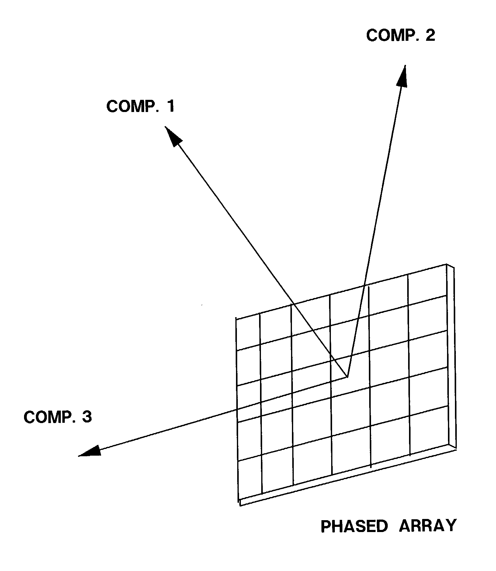
[0023]The present invention relates to transmitting different information on different multipath components that exist between a transmitting station and a receiving station, while not requiring the receiving station to have a sophisticated antenna. The invention can be dynamic in that it can very quickly change the set of multipath components being used in a fast burst mode environment (such as in typical burst code or time division multiple access system CDMA or TDMA). FIG. 1 shows a diagram of such a system with a transmitting station 1 and a receiving station 2.

[0024]A “smart” transmitting antenna 3, or set of antennas, can be used at a base-station (which can be a cellular telephone base-station) to selectively transmit different information in different angular directions that have been mapped as multipath components 5 to the desired receiver 2 (which can be a cellular telephone). Usually the receiver 2 contains an omni-directional antenna 4. The transmissions can optionally b...


PUM


Abstract

A method and system for increasing the throughput of a wireless channel that sends different data on different multi-path components. The channel can be pre-mapped or dynamically mapped, and the different transmissions can be modulated by different complexity signals such as adaptive quadrature amplitude modulation (AQAM). Each multipath component is coded with a signature that will allow it to be separated at a receiver that has an omni-directional antenna. Common signature techniques can be offset PN codes, orthogonal spreading vectors, orthogonal alphabets and other signature techniques. The received channels can be combined for an overall increase in data-rate or used separate as multiplexed data.

Description

BACKGROUND[0001]1. Field of the Invention[0002]The present invention relates generally to the field of wireless communication and more particularly to a method and apparatus for enhancing the throughput of a wireless communication system by using multipath transmission.[0003]2. Description of the Related Art[0004]Generally when radio waves leave a wireless radio transmitter, they spread out in all directions away from the transmitter. There is usually a direct path from the transmitting station to a receiving station. Some of the transmitted radio energy follows this direct path; however, a portion of the energy follows other paths. The phenomenon of more than one path for radio transmission between two stations is called multipath. Each path is called a multipath component. In particular, multipath is the arrival at the receiver of radio waves from the transmitter that followed various paths from the transmitter to the receiver. The reason for this effect is that radio waves reflec...

Claims


Application Information

Patent Timeline
Patent Type & Authority Patents(United States)
IPC IPC(8): H03C7/00H03K7/06H04L27/20
CPCH04L25/14H04B1/711H04L27/3405
Inventor KRAFT, CLIFFORDDOSSAS, VASILIOS D.
Owner KRAFT CLIFFORD
Why Eureka
Try Eureka