
Method and system for controlling an electric motor with variable switching frequency at variable operating speeds

a technology of electric motors and operating speeds, applied in the direction of motor/generator/converter stoppers, dynamo-electric converter control, pulse technique, etc., can solve the problems of increasing the switching loss of inverters, increasing the data processing burden of data processors or digital signal processors within inverters, and reducing the life of inverters

Active Publication Date: 2013-06-04
DEERE & CO
View PDF19 Cites 12 Cited by
  • Summary
  • Abstract
  • Description
  • Claims
  • Application Information

AI Technical Summary

Benefits of technology

This patent describes a method and system for controlling an electric motor. The system includes a data processor that sets a range of speeds for the motor's rotor, called a hysteresis band. The processor uses sensors to measure the motor's speed and adjusts the speed range accordingly. The system then uses a pulse-width modulation signal to vary the switching frequency of the electric motor in relation to the desired speed range. This allows for smoother and more efficient operation of the electric motor.

Problems solved by technology

Although, to some extent, motor control performance can be increased with an increase in pulse width modulation switching frequency provided by the inverter, an excessively high switching frequency increases inverter switching losses, reduces inverter life from thermal impact, and increases the data processing burden of the data processor or digital signal processor within the inverter.

Method used


Image

  • Method and system for controlling an electric motor with variable switching frequency at variable operating speeds
  • Method and system for controlling an electric motor with variable switching frequency at variable operating speeds
  • Method and system for controlling an electric motor with variable switching frequency at variable operating speeds

Examples


Embodiment Construction

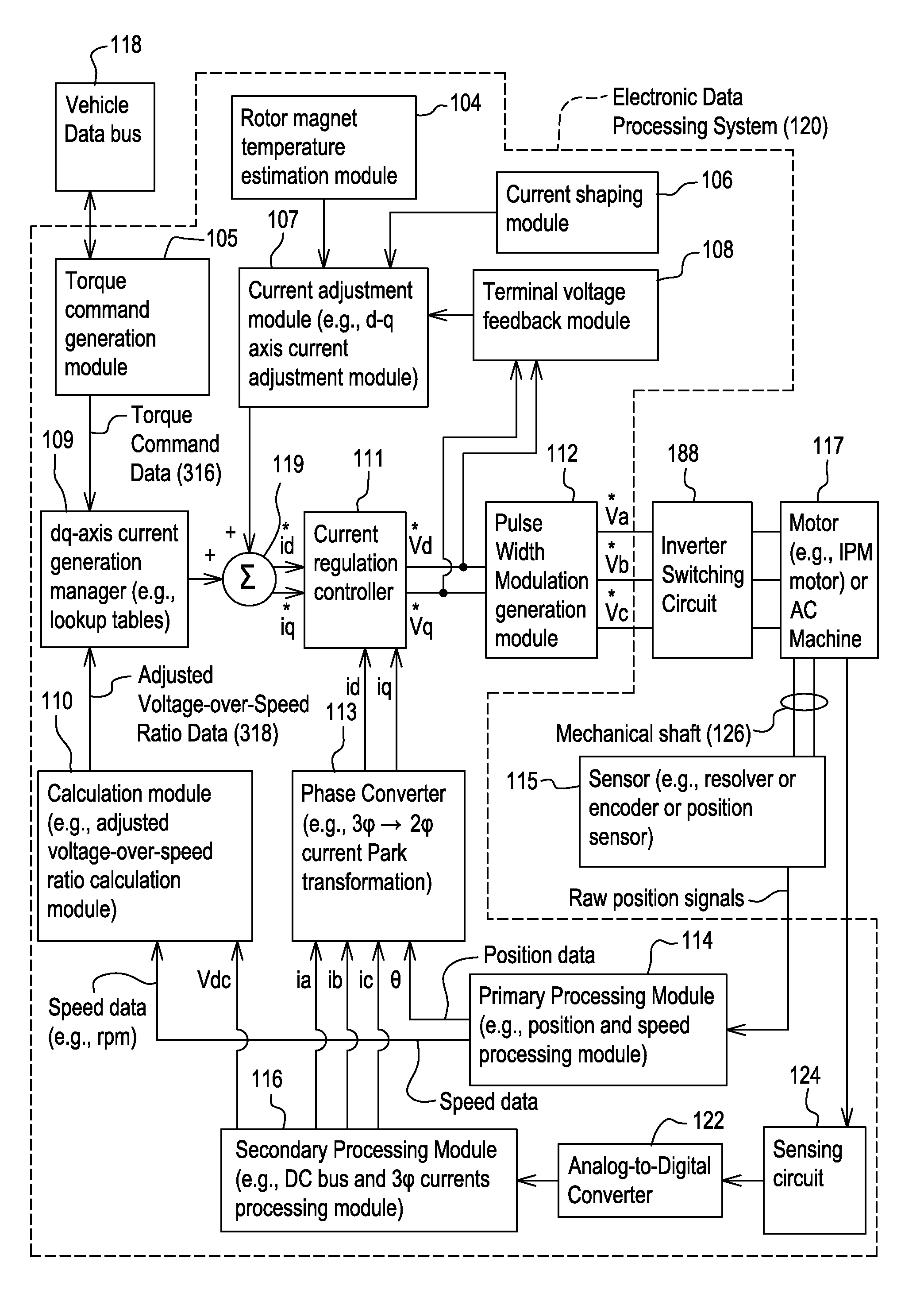
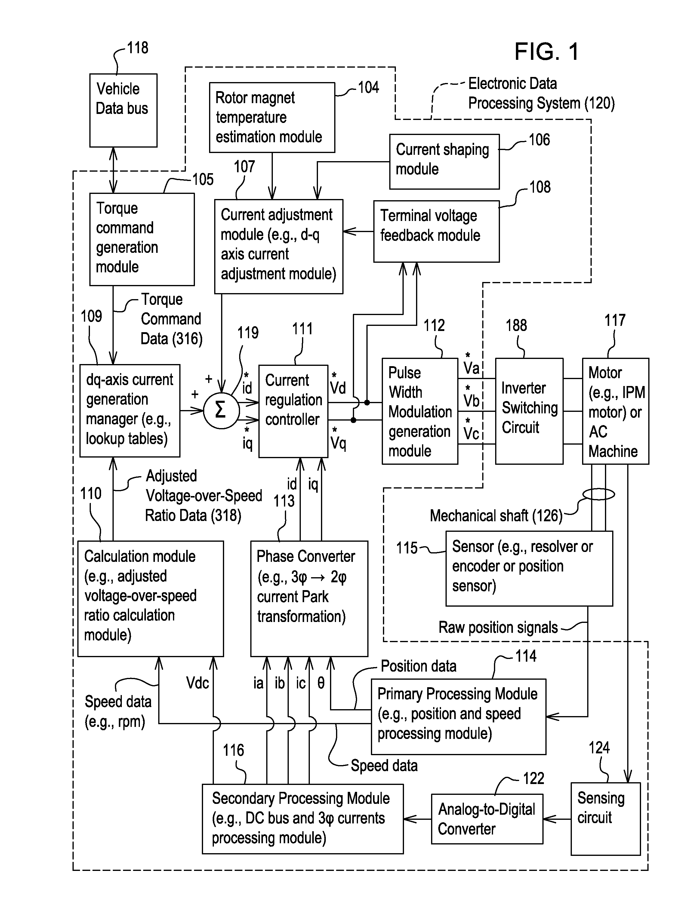
[0011]In accordance with one embodiment, FIG. 1 discloses system for controlling a motor 117 (e.g., an interior permanent magnet (IPM) motor) or another alternating current machine. The method and system described in this document can be equally applied to, interior permanent magnet motors, induction machines, or surfaced mounted permanent magnet (PM) machines with wide operating speeds. In one embodiment, the system, aside from the motor 117, may be referred to as an inverter or a motor controller. The system or inverter is well-suited for a widely varying operating speed of the motor shaft such that a balanced or optimum pulse width modulation frequency is selected for the inverter in one or more different speed ranges.

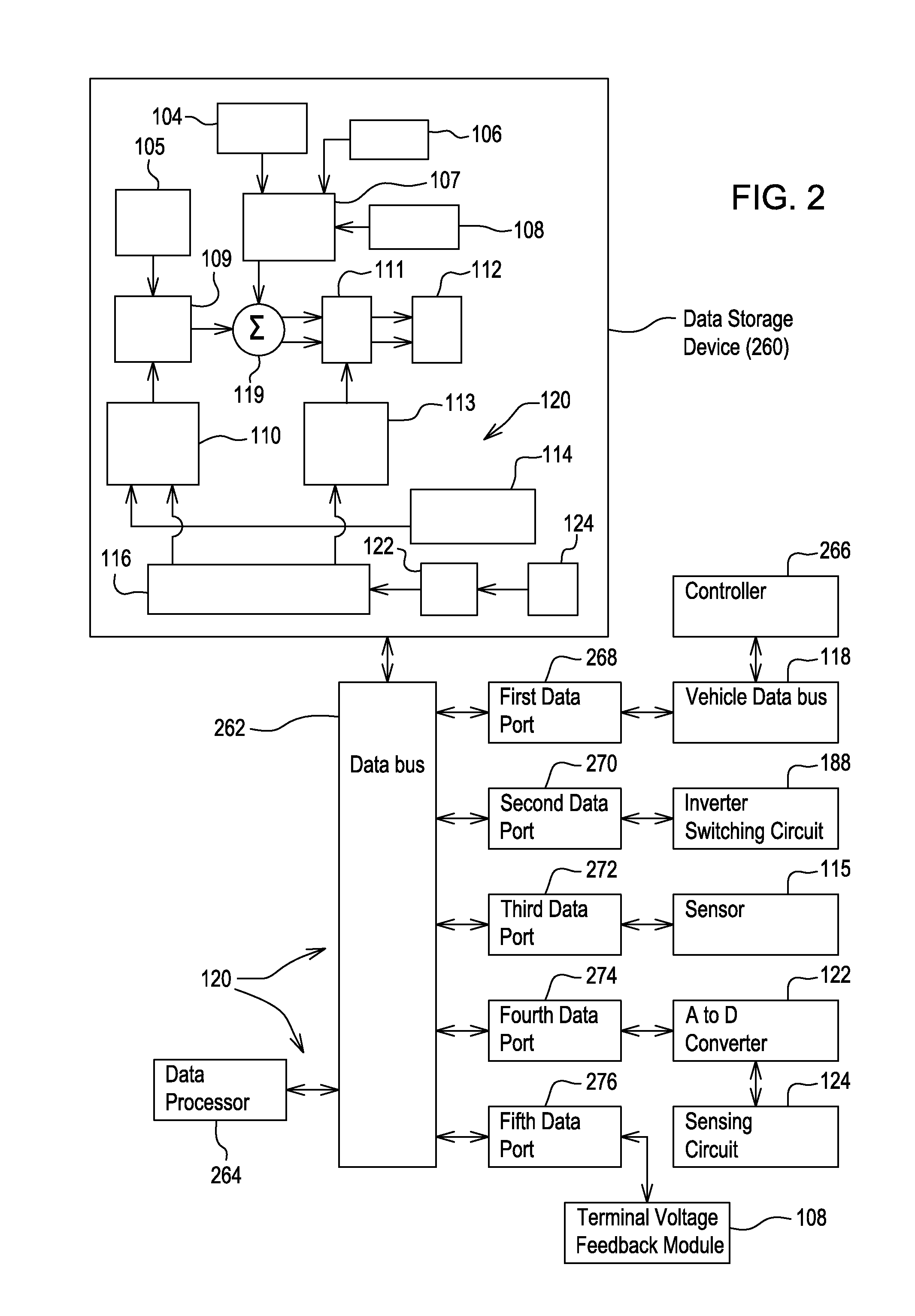
[0012]The system comprises electronic modules, software modules, or both. In one embodiment, the motor controller comprises an electronic data processing system 120 to support storing, processing or execution of software instructions of one or more software modules....


PUM


Abstract

A data processor establishes a first range of rotational speeds of a rotor of the motor from a first lower limit to a first higher limit and a second range of rotational speeds from a second lower limit to a second higher limit. A hysteresis band or a rotational range of speeds is established such that during operation in the first range the first higher limit is adjusted (e.g., raised by a first amount to be greater than the second lower limit). A sensor detects or measures a rotational speed of a rotor of the motor. The data processor determines whether the measured rotational speed falls within the first range or the second range, as adjusted by the hysteresis band, to identify a selected speed range. A switching frequency of a pulse-width modulation signal is varied in accordance with the selected speed range.

Description

[0001]This document claims priority based on U.S. provisional application Ser. No. 61 / 445,632, filed on 23 Feb. 2011 and entitled METHOD AND SYSTEM FOR CONTROLLING AN ELECTRIC MOTOR WITH VARIABLE SWITCHING FREQUENCY AT VARIABLE OPERATING SPEEDS, under 35 U.S.C. 119(e).FIELD OF THE INVENTION[0002]This invention relates to a method and system for controlling an electric motor with variable switching frequency (e.g., pulse width modulation frequency) at variable operating speeds of a motor shaft.BACKGROUND OF THE INVENTION[0003]An electric motor may feature a rotor with permanent magnets and a stator, such as an interior permanent magnet (IPM) motor or an IPM synchronous motor. Application of the motor to a vehicle traction often requires a wide speed range of motor control. Although, to some extent, motor control performance can be increased with an increase in pulse width modulation switching frequency provided by the inverter, an excessively high switching frequency increases invert...

Claims


Application Information

Patent Timeline
Patent Type & Authority Patents(United States)
IPC IPC(8): H02P6/14
CPCH02P6/14
Inventor WU, LONGSHAW, ROBERT
Owner DEERE & CO
Learn More