Device for gasification and combustion of solid fuel

a combustion device and solid fuel technology, applied in the details of gasification processes, combustion treatment, washing apparatus, etc., can solve the problems of disturbing the combustion process, affecting the efficiency of the combustion process, and the combustion of pellets presently, so as to achieve simple and efficient, reduce the outside surface temperature of the combustion device, and improve efficiency.

Active Publication Date: 2013-06-11
AHOLA KIMMO
View PDF18 Cites 2 Cited by
  • Summary
  • Abstract
  • Description
  • Claims
  • Application Information

AI Technical Summary

Benefits of technology

[0008]The combustion device according to the invention is simple and efficient, due in particular to the separate cylindrical reactor tube placed vertically on the partition and open at both ends, enabling an optimum gasification of the fuel in a reactor tube that is spaced from exterior walls of the reactor space. By virtue of the above, outside surface temperatures of the combustion device can be minimized and the efficiency can be significantly improved. Pellets are fed to the grate as needed in response to an optical detector in the top of a pellet feed chute over the reactor tube, and are not piled high over the grate, so that they are not highly heated prior to being fed and do not disintegrate. This represents an important advantage over Ohlsson U.S. Pat. No. 2,354,963.
[0009]The invention furthermore has the advantage that the rate of product gas being gasified from the solid fuel will increase, so that higher flame and radiation temperatures in the combustion tube will be achieved. Further, the shape of the burner's flame has a wide cross section and is elongated, so it is useful in many kinds of boilers. Also, very little flue dust is generated, which reduces particulate emission of the burner so that the need for chimney sweeping of the smoke flue also decreases. The combustion process of the combustion device according to the invention is more like an oil burner than traditional pellet burners, whereby it offers a viable alternative when renewing heating systems.

Problems solved by technology

Several problems arise with pellet burners presently in use, and with the combustion of pellets.
Ash remains in place and easily gets mixed with new pellets added into the combustion space, thus disturbing the combustion process.
Due to incomplete combustion and low combustion temperature, a large amount of flue gas develops and the burner efficiency remains low.
Additionally, the amount of residual oxygen in the flue gas exhausted from the burner is very high.
Removal of ash is particularly laborious, when the pellet burner is mounted in an old oil boiler, where removal of ash was not originally considered.
Note that this device would not be suitable for burning pellets, because of the high temperatures in the feed column, which would cause pellets to disintegrate long before they reach the grate.
None of the devices described above significantly decreases the problems related to gasification of solid fuel, particularly with regard to feeding of secondary air into the product gas and / or the structural solutions of the reactor space, because a mixing of combustion air and product gas that is sufficient to ensure complete combustion and optimum efficiency cannot be achieved.

Method used


Image

  • Device for gasification and combustion of solid fuel
  • Device for gasification and combustion of solid fuel
  • Device for gasification and combustion of solid fuel

Examples


Embodiment Construction

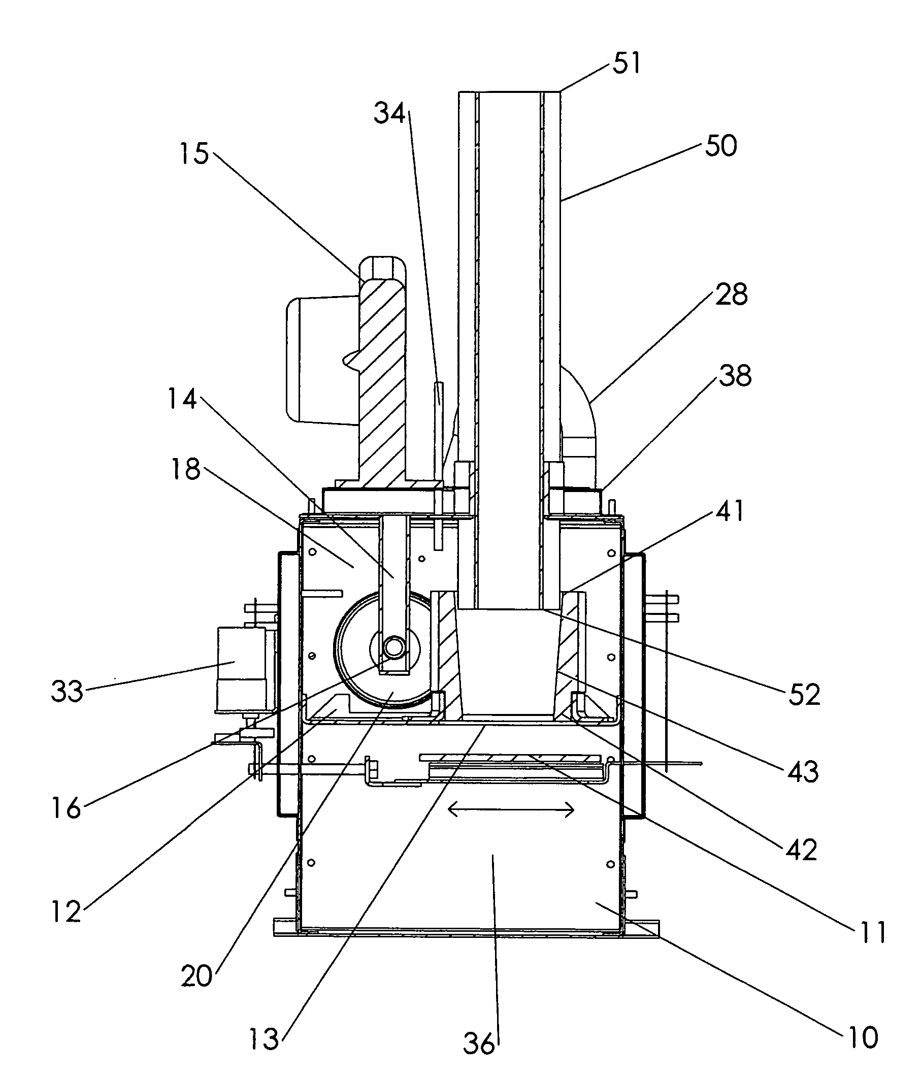
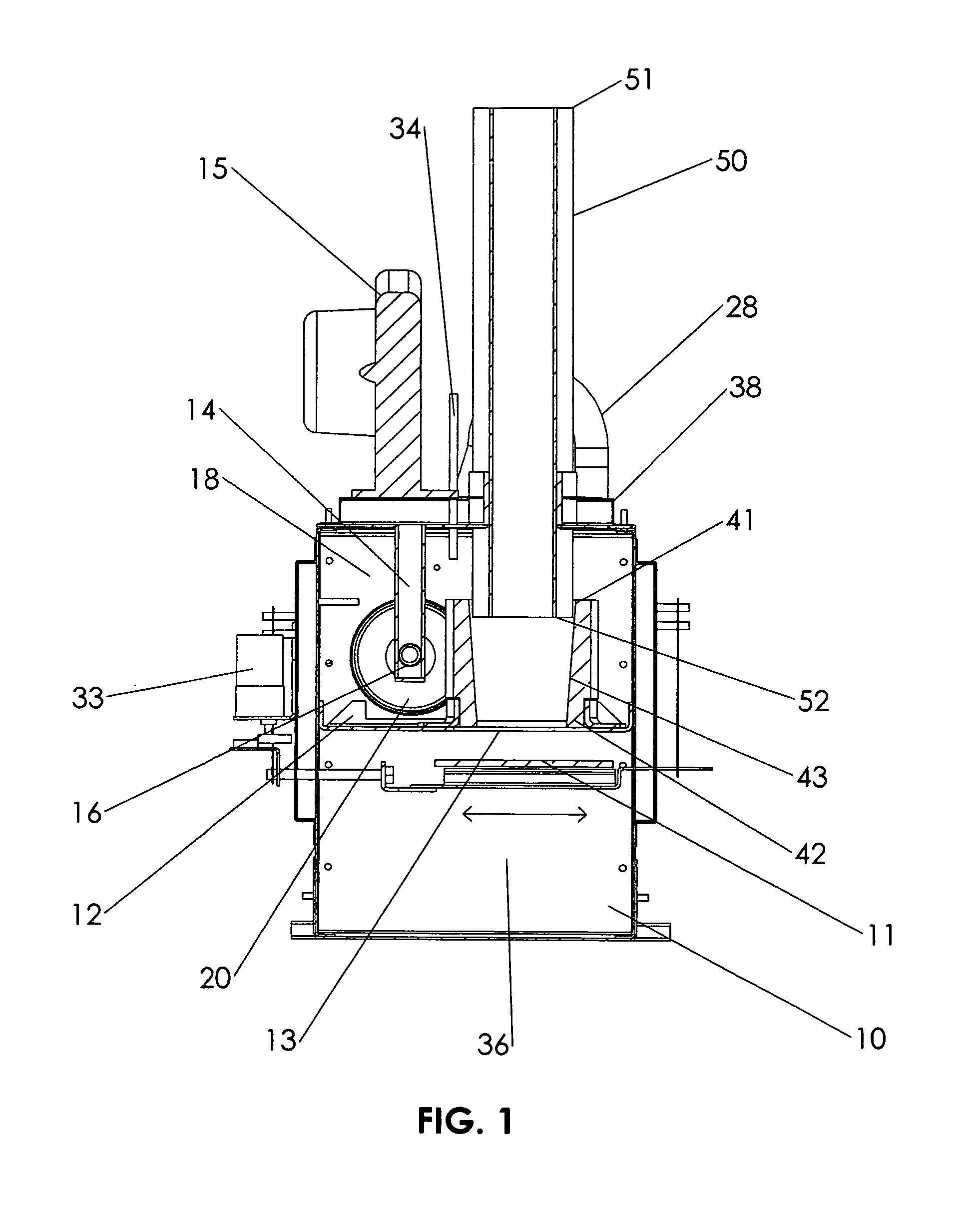
[0015]Referring to FIG. 1, the combustion device includes an enclosure 10 having walls formed of steel sheet and fastened to a frame in known fashion. The walls may be coated on the inside and / or the outside with thermal insulation. A substantially horizontal partition 12 formed of sheet steel, preferably stainless steel plate, divides the enclosure into an upper space 18 and a lower space 19. The partition 12 has a hole 13 which provides essentially the only passage for flow of gas from the lower space to the upper space. A reactor tube 40 having an open upper end 41 in the upper space 18 and an open lower end 42 is supported on the partition 12 concentrically over the hole 13. A grate 11, preferably made of ceramic, is located in the lower space 19 below the hole 13, and is spaced 1.5 to 2.5 cm from the partition 12. A fuel feed chute 50 has an open upper end 51 for connecting to a supply of pellets to form an airtight feed system, and an open lower end 52 that projects into the r...


PUM


Abstract

A partition divides an enclosure into an upper space and a lower space, the partition having a hole which provides essentially the only passage for gas to flow from the lower space to the upper space. A reactor tube having open ends is supported by the partition over the hole, and a grate spaced below the hole. A primary air inlet arrangement feeds air into the lower space for gasification of solid fuel on the grate, and a secondary air inlet directs a jet of air toward the inlet end of combustion tube communicating with the upper space and having an open exhaust end outside the enclosure. Product gas formed by gasification of solid fuel on the grate and passing through the reactor tube into the upper space will be drawn into the combustion tube to create a sub-atmospheric pressure in the upper space.

Description

FIELD OF THE INVENTION[0001]The invention relates to a combustion device for gasification and combustion of solid fuel, in particular to a pellet burner, of the type having a grate which receives the solid fuel, a primary air inlet arrangement which provides air to the grate for gasification of the solid fuel to form product gas, and a secondary air inlet arrangement for blowing a stream of air into a combustion tube in order to draw product gas into the combustion tube and lower the pressure in the reactor space.DESCRIPTION OF THE RELATED ART[0002]A typical pellet heating system includes a boiler with water circulation, a pellet burner, and a system for storing and transferring pellets. The boiler can be designed for an oil burner or can be intended particularly for combustion of solid fuel, such as a multi-fuel boiler or a boiler designed particularly for burning of pellets. The known pellet burners can be divided into three different main types depending on the feed inlet of pell...

Claims


Application Information

Patent Timeline
Patent Type & Authority Patents(United States)
IPC IPC(8): F23G5/027F23G7/00F23D14/20
CPCC10J3/40F23G5/027F23G5/245C10J2200/09C10J2200/15C10J2300/0903C10J2300/0916C10J2300/0956C10J2300/1276C10J2300/1606F23G2201/303F23G2203/401
Inventor AHOLA, KIMMO
Owner AHOLA KIMMO
Why Eureka
Try Eureka