
Recording head with near field transducer having non-rectangular pin cross section

a near field transducer and cross section technology, applied in the field of magnetic read/write heads, can solve the problems of increasing coercivity, increasing and reducing the grain size soon reaches the “superparamagnetic limit”, so as to improve the trailing edge of the thermal spo

Active Publication Date: 2013-06-25
WESTERN DIGITAL TECH INC
View PDF36 Cites 154 Cited by
  • Summary
  • Abstract
  • Description
  • Claims
  • Application Information

AI Technical Summary

Benefits of technology

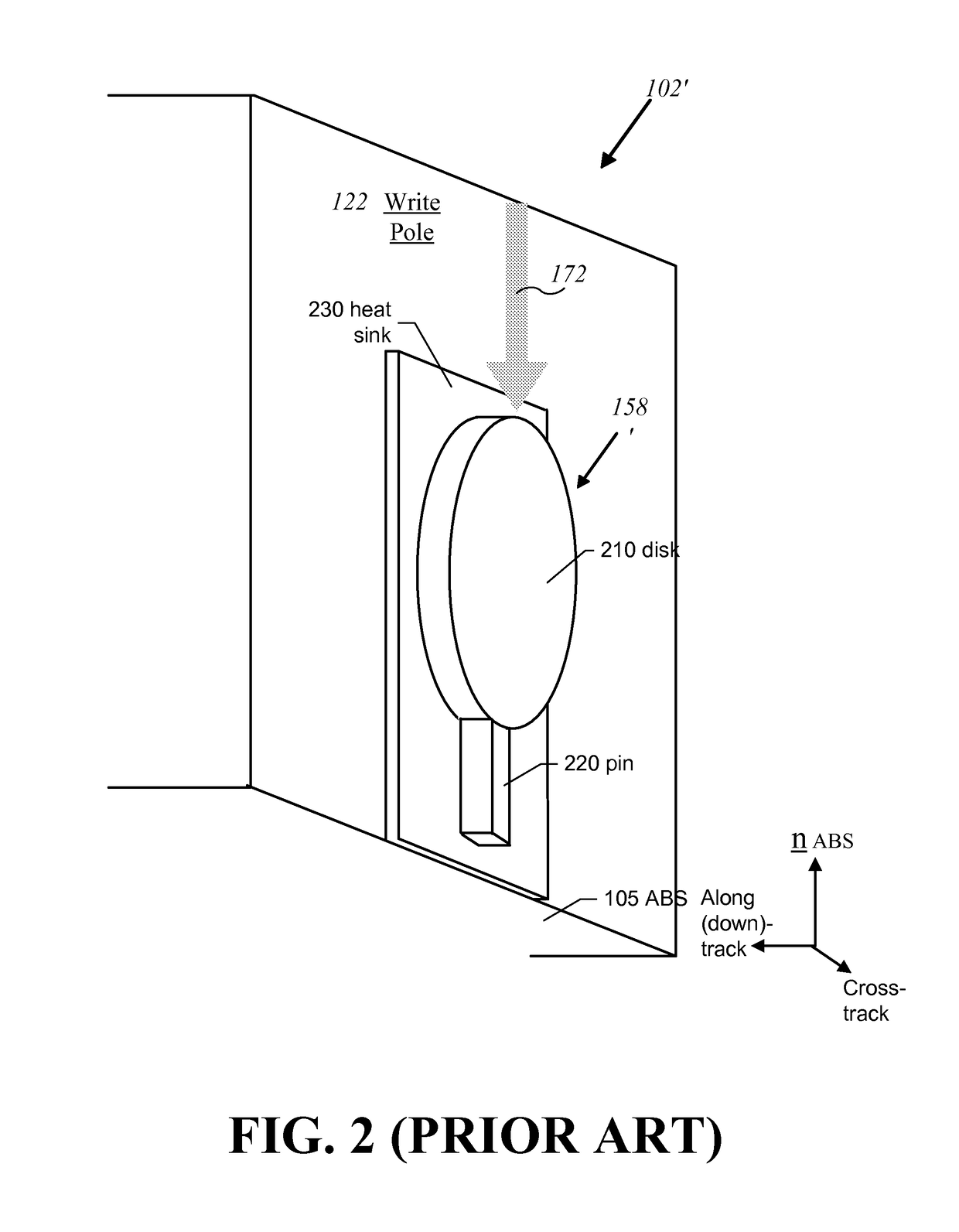
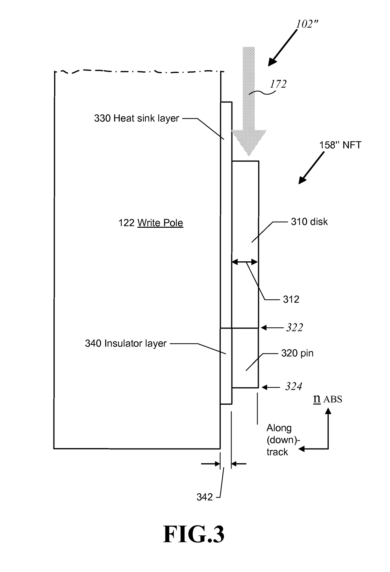
The patent text describes a near field transducer (NFT) and an energy assisted magnetic recording (EAMR) head for writing to a recording media. The NFT is a device that helps to direct energy to a specific part of the recording media. The NFT has a pin section that is connected to a disk section and extends towards the air bearing surface (ABS) of the NFT. The pin section has a non-rectangular cross section in a plane parallel to the ABS. The technical effect of this design is that it improves the accuracy and efficiency of the EAMR head in writing to the recording media.

Problems solved by technology

This reduction in grain size soon reaches a “superparamagnetic limit,” at which point the magnetic grains become thermally unstable and incapable of maintaining their magnetization.
Increasing the magnetic anisotropy of the magnetic grains, however, increases their coercivity and therefore requires a stronger magnetic field to change the magnetic orientation of the grains (e.g., in a write operation).
Design challenges for these grating structures include improving their coupling efficiency and the difficulty in aligning a light source for high volume manufacturing processes.
Fabrication of portions of the conventional NFT, at such small sizes may be challenging.
In addition, with a conventional NFT arrangement, the trailing edge of the thermal spot has a high degree of curvature, which limits the track density due to SNR degradation from the track curvature.

Method used


Image

  • Recording head with near field transducer having non-rectangular pin cross section
  • Recording head with near field transducer having non-rectangular pin cross section
  • Recording head with near field transducer having non-rectangular pin cross section

Examples


Embodiment Construction

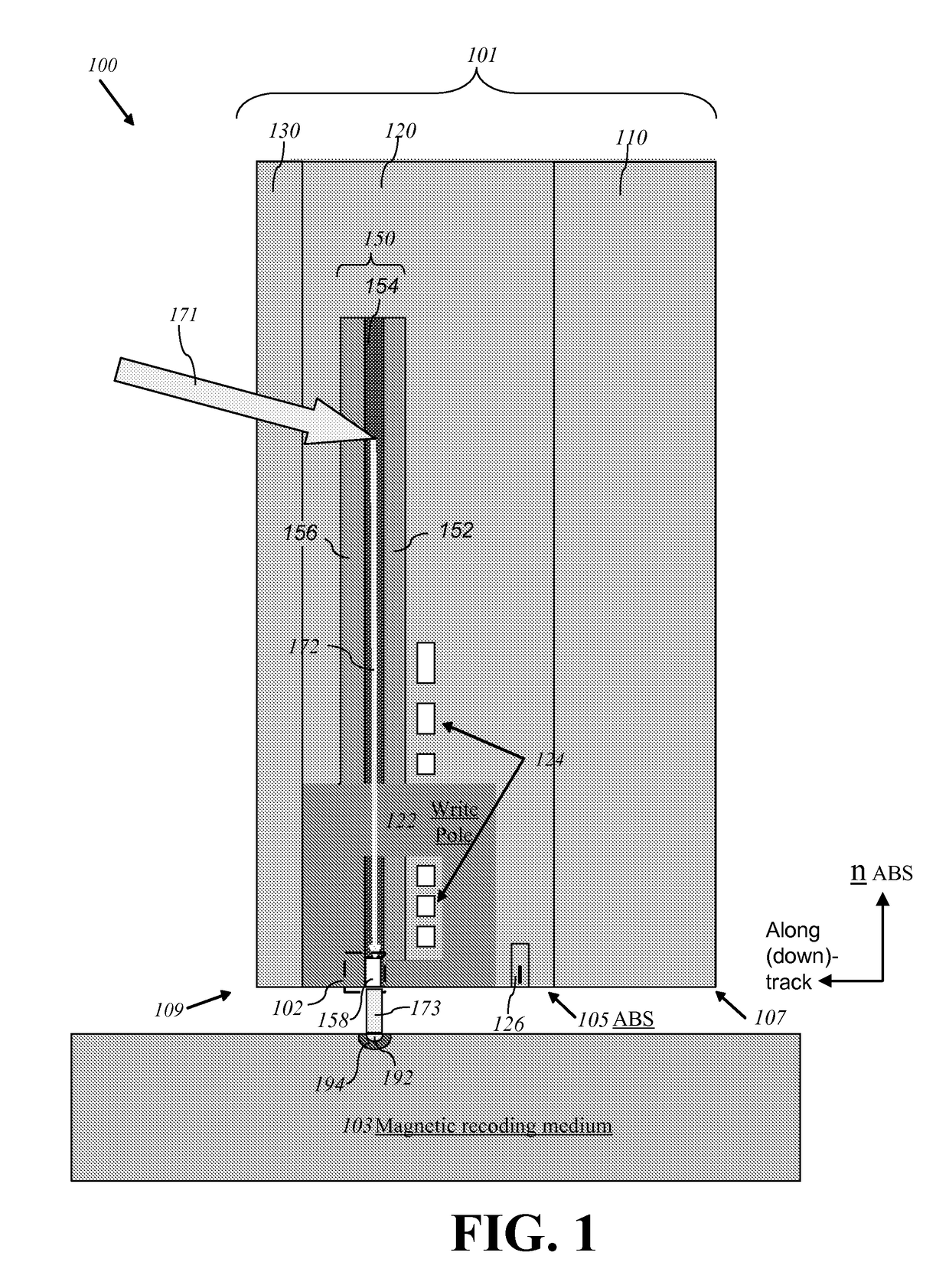
[0017]FIG. 1 is a diagram depicting a cross-sectional view of an exemplary EAMR head 100 according to certain aspects of the subject disclosure. The EAMR head 100 comprises a slider 101. The slider 101 comprises a substrate 110, a recorder / reader layer 120 disposed over the substrate 110, and an overcoat layer 130 disposed over the recorder / reader layer 120. In certain embodiments, the substrate 110 comprises AlTiC and the overcoat layer 130 comprises alumina. The slider 101 has a leading edge 107 and a trailing edge 109, and an air-bearing surface (ABS) 105 facing a magnetic recording medium 103. The recorder / reader layer 120 of the slider 101 includes a write pole 122 for recording or erasing information on the medium 103 by focusing a magnetic field on a spot on the medium 103, a coil 124 for generating the magnetic field, a reader 126 for reading a magnetic bit recorded on the medium 103, and a waveguide structure 150. The waveguide structure 150 includes a first, top clad layer...


PUM

PropertyMeasurementUnit
thicknessaaaaaaaaaa
thicknessaaaaaaaaaa
widthaaaaaaaaaa

Abstract

A near field transducer (NFT) for use in an energy assisted magnetic recording (EAMR) head and configured to direct energy to a recording media is disclosed. The NFT comprises a disk section; and a pin section extending towards an air bearing surface (ABS) from the disk section. The pin section has a proximal end adjoining the disk section and a distal end opposite to the proximal end and facing the ABS, wherein the distal end of the pin section has a non-rectangular cross section in a plane parallel to the ABS and the proximal end of the pin section has a rectangular cross section in the plane parallel to the ABS.

Description

CROSS-REFERENCE TO RELATED APPLICATIONS[0001]This application is a divisional of U.S. patent application Ser. No. 12 / 794,692, filed on Jun. 4, 2010, which is hereby incorporated by reference in its entirety.FIELD OF THE INVENTION[0002]The present invention generally relates to magnetic read / write heads and, in particular, relates to trailing edge near field transducers having non-rectangular pin cross sections.BACKGROUND[0003]To increase the areal storage density of a magnetic recording device, the recording layer thereof may be provided with smaller and smaller individual magnetic grains. This reduction in grain size soon reaches a “superparamagnetic limit,” at which point the magnetic grains become thermally unstable and incapable of maintaining their magnetization. The thermal stability of the magnetic grains can be increased by increasing the magnetic anisotropy thereof (e.g., by utilizing materials with higher anisotropic constants). Increasing the magnetic anisotropy of the ma...

Claims


Application Information

Patent Timeline
Patent Type & Authority Patents(United States)
IPC IPC(8): G11B11/00
CPCG11B5/314G11B5/6088G11B2005/0021
Inventor WOLF, CHRISTOPHER B.CHAMPION, ERIC J.STOEV, KROUM S.
Owner WESTERN DIGITAL TECH INC
Learn More