Electrical stimulation method for reduction of joint compression

a joint compression and electric stimulation technology, applied in electrotherapy, external electrodes, therapy, etc., can solve the problems of joint pain and/or stiffness, joint deformation, degeneration or “wear and tear” of articular cartilage, etc., to reduce joint compression and reduce co-contraction

Inactive Publication Date: 2013-06-25
ACCELERATED CARE PLUS CORP
View PDF10 Cites 16 Cited by
  • Summary
  • Abstract
  • Description
  • Claims
  • Application Information

AI Technical Summary

Benefits of technology

[0030]A signal's frequency can be calculated in several possible ways, including via Fourier (and more easily implemented fast Fourier transform (“FFT”)) transforms, measuring signal amplitude after band pass filtering, and via half waves. Thus, in another aspect, the reduction of joint compression is shown by decreased co-contraction in opposing muscle groups associated with a joint (agonist and antagonist) as measured by muscle hardness and / or FFT patterns. Higher mean frequencies and frequency spectrums indicates that the muscle is firing harder.

Problems solved by technology

A common form of joint pain and / or stiffness arises from the unwanted co-contraction of muscles.
The co-contraction causes joint compression, which results in the degeneration or “wear and tear” of articular cartilage and is usually accompanied by an overgrowth of bone, narrowing of the joint space, sclerosis or hardening of bone at the joint surface, and deformity in joints.
Weight bearing joints, such as the knees and hips, are particularly susceptible to osteoarthritis.
Unwanted involuntary muscle co-contraction, as a response to an abnormal stimulus such as pain during joint movement, can be destructive to the joint over time.
The starved articular cartilage deteriorates, which leads to additional pain, decreased coordination, increased joint stiffness, and eventual total joint degeneration.

Method used


Image

  • Electrical stimulation method for reduction of joint compression
  • Electrical stimulation method for reduction of joint compression
  • Electrical stimulation method for reduction of joint compression

Examples


first exemplary embodiment

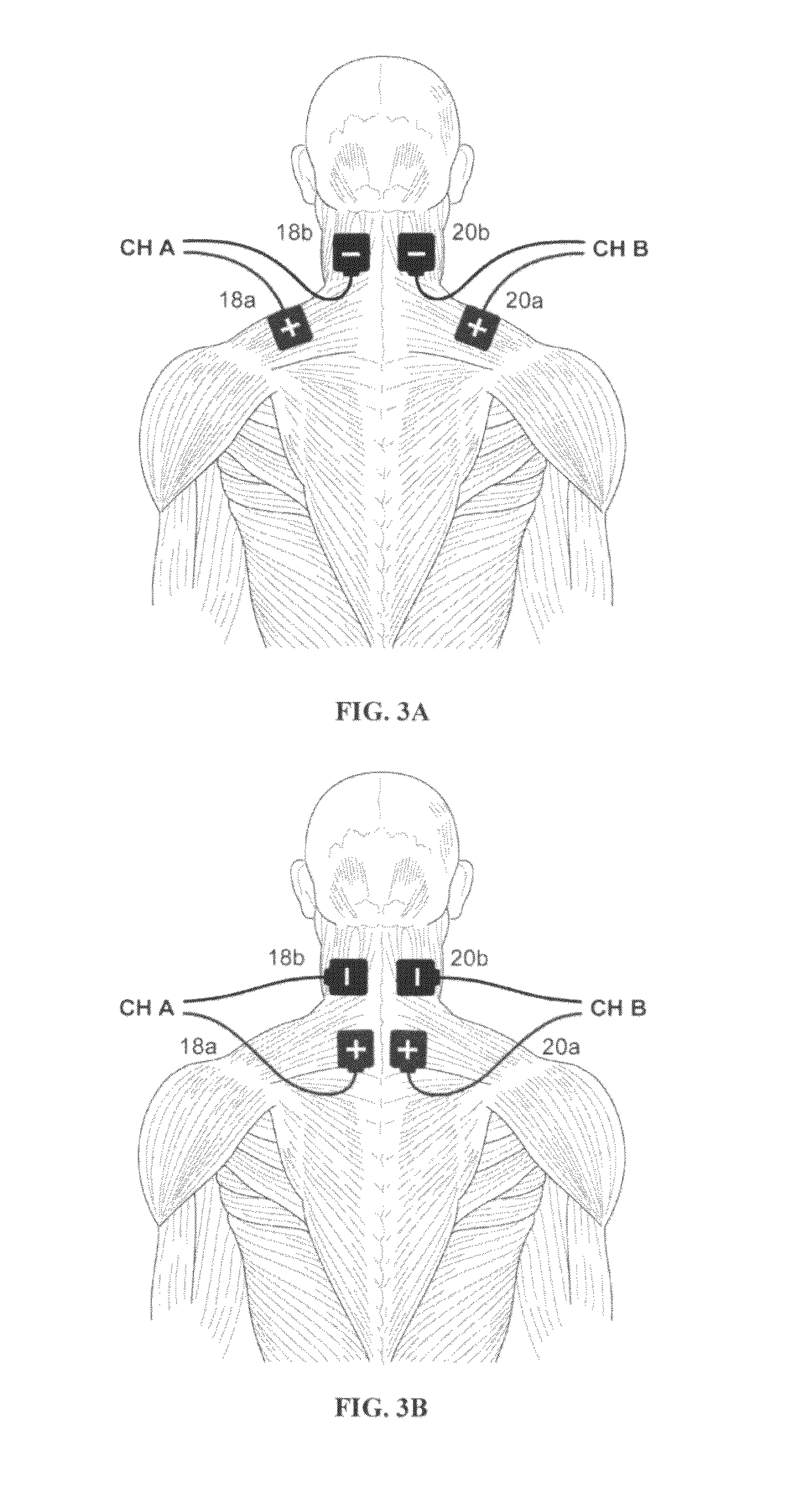
[0102]In a first exemplary embodiment of the present invention, as generally illustrated in FIG. 3A, a pair of electrodes is positioned in electrical contact with the patient's tissue in order to provide electrical stimulation to one or more of the muscles associated with intervertebral and shoulder joint movement. A second pair of electrodes is positioned bilaterally in a similar manner.

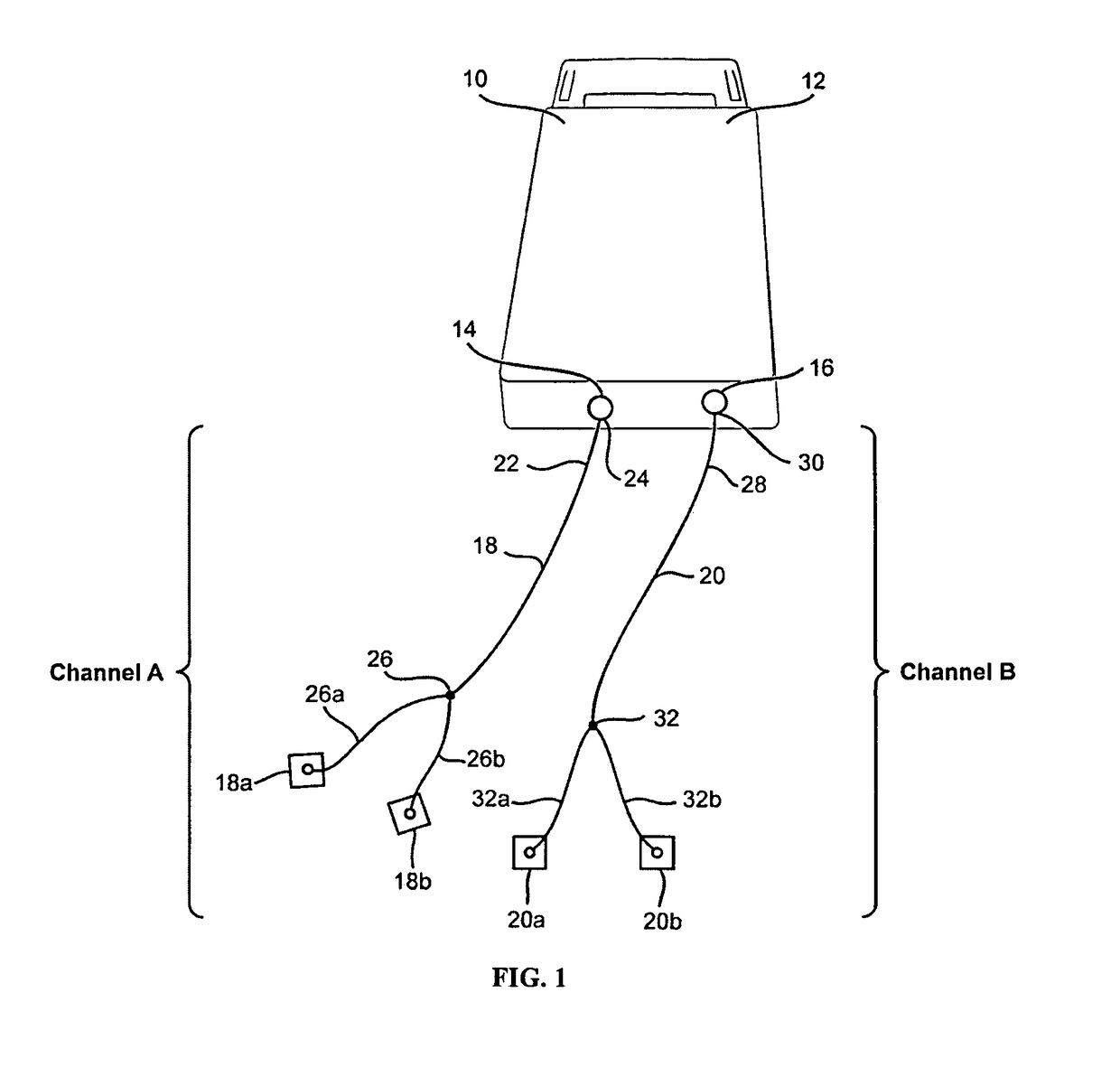
[0103]More specifically, as shown in FIG. 3A, a two-channel system is used to apply electrical stimulation to agonist / antagonist muscles involved in neck intervertebral and shoulder joint movement. For the first channel, a first electrode 18a is positioned in electrical contact with tissue to stimulate a motor point of the patient's upper trapezius muscle. Most preferably, first electrode 18a comprises a surface electrode that is positioned on the patient's skin along the midpoint of the upper trapezium. A second electrode 18b is positioned is electrical contact with tissue to stimulate a motor poin...

second exemplary embodiment

[0114]In a second exemplary embodiment of the present invention, as generally illustrated in FIG. 3B, two pairs of electrodes are positioned in electrical contact with the patient's tissue in order to provide electrical stimulation to one or more of the muscles associated with intervertebral and shoulder joint movement

[0115]More specifically, as shown in FIG. 3B, a two-channel system is used to apply electrical stimulation to agonist / antagonist muscles involved in neck intervertebral and shoulder joint movement. For the first channel, a first electrode 118a is positioned in electrical contact with tissue to stimulate a motor point of the patient's lower cervical and upper thoracic paraspinal muscles. Most preferably, first electrode 18a comprises a surface electrode that is positioned on the patient's skin along the midpoint of the upper trapezius just lateral to the spinal cord, most preferably near the C6, C7, T1, T2, T3, and / or T4 cervical and thoracic vertebrae. A second electro...

third exemplary embodiment

[0126]In a third exemplary embodiment of the present invention, as generally illustrated in FIG. 3C, two pairs of electrodes are positioned in electrical contact with the patient's tissue in order to provide electrical stimulation to one or more of the muscles associated with intervertebral joint movement.

[0127]More specifically, as shown in FIG. 3C, a two channel system is used to apply electrical stimulation to agonist / antagonist muscles involved in upper and mid-back intervertebral joint movement including the erector spinae and trapezius muscles. For the first channel, a first electrode 18a is positioned in electrical contact with tissue to stimulate a motor point of the patient's thoracic paraspinal muscles. Most preferably, first electrode 18a comprises a surface electrode that is positioned on the patient's skin just lateral to one or more thoracic vertebrae, most preferably near the T3, T4, T5, T6, T7, T8, and / or T9 thoracic vertebrae. A second electrode 18b is positioned in...


PUM


Abstract

An electrical stimulation method for the reduction of joint compression utilizes an electrical stimulation device that includes a plurality of channels of electrodes each of which includes at least a first and second electrode positioned in electrical contact with tissue of at least two muscles crossing a joint. Agonist / antagonist muscles involved in abduction / adduction, flexion / extension, supination / pronation, protraction / retraction, and / or eversion / inversion of body regions via joint movement are stimulated with a patterned series of electrical pulses through channels of electrodes in accordance with a procedure for reducing joint compression. The patterned series of electrical pulses may comprise: a plurality of cycles of a biphasic sequential pulse train pattern; a plurality of cycles of a biphasic overlapping pulse train pattern; a plurality of cycles of a triphasic sequential pulse train pattern; and a plurality of cycles of a triphasic overlapping pulse train pattern.

Description

CROSS-REFERENCE TO RELATED APPLICATIONS[0001]Not applicable.STATEMENT REGARDING FEDERALLY SPONSORED RESEARCH OR DEVELOPMENT[0002]Not applicable.FIELD OF THE INVENTION[0003]The present invention is generally directed to a method for reducing joint compression, and is more specifically directed to an electrical stimulation method for applying a patterned series of electrical pulses to a plurality of channels of electrodes in accordance with a procedure for reducing joint compression. The method results in improved muscle and nerve timing, which reduces co-activation of muscles associated with joints during movement or during stabilization.DESCRIPTION OF RELATED ART[0004]The junction of two or more bones or skeletal parts is a joint. There are several types of human joints including fibrous (non-movable), cartilaginous (connected entirely by cartilage), and synovial joints. A synovial joint is a freely movable articulation, in which contiguous bone surfaces are covered with collagenous...

Claims


Application Information

Patent Timeline
Patent Type & Authority Patents(United States)
IPC IPC(8): A61N1/04
CPCA61N1/0452A61N1/36003A61N1/36014A61N1/36034A61N1/36031
Inventor CASTEL, J. CHRISPALERMO, FRANK
Owner ACCELERATED CARE PLUS CORP
Why Eureka
Try Eureka