
Device and method for particle therapy verification

a particle therapy and device technology, applied in the field of charged hadron therapy, can solve the problems of inability to direct detection of the end of the dose deposition of a hadron beam, and the inability to fully take into account the complex atomic composition of surrounding tissues

Inactive Publication Date: 2013-07-09
ION BEAM APPL
View PDF8 Cites 25 Cited by
  • Summary
  • Abstract
  • Description
  • Claims
  • Application Information

AI Technical Summary

Problems solved by technology

Even if existing radiation treatment planning tools calculate a “theoretical” or “planned” beam range and dose distribution based on CT images, it is almost impossible to fully take into account the complex atomic composition of surrounding tissues.
As a consequence, a degree of uncertainty is affecting the particle range.
The direct detection of the end of the dose deposition of a hadron beam is impossible since the hadron beam stops inside the treatment volume, even during the irradiation.
For proton beams this principle can not be used due to differences in the mechanisms for producing PET isotopes with proton beams when compared with carbon beams.
Moreover, the leakage of positron emitters to the blood flow will also affect the dose deposition measurement by off-beam PET scanning.
Nevertheless, this device is only able to detect prompt gamma emitted from 90° of the beam direction.
To obtain the prompt gamma distribution along the beam direction, the detector needs to be moved step by step to different measurement positions which makes this device not useful for practical on-line measurements.
One of the disadvantages of this device is the increased level of background as result of reduced collimator shielding.

Method used


Image

  • Device and method for particle therapy verification
  • Device and method for particle therapy verification
  • Device and method for particle therapy verification

Examples


embodiment 1

[0126]In one preferred embodiment an Anger camera (10) is used to detect the prompt gammas emitted in a direction essentially at 90° with respect to the beam direction.

[0127]The camera (10) is installed such that its optical axis (9) is perpendicular to the beam direction, in order to detect prompt gammas emitted from the object at 90°.

[0128]The same principle can be used by putting the camera in a different geometry with respect to the beam direction and measuring prompt gammas at different angles.

[0129]The Anger camera (10) is equipped with appropriate shielding against neutrons, X-ray and unwanted gamma-rays.

[0130]As depicted in FIG. 4 the camera (10) comprises a plurality of collimators (1) that are made of high atomic number material such as Pb or W, on top of which at least one scintillating crystal (2) is laid.

[0131]The at least one scintillating crystal is optically coupled to at least one photomultiplier tube (3), each of them being connected to appropriate readout electron...

embodiment 2

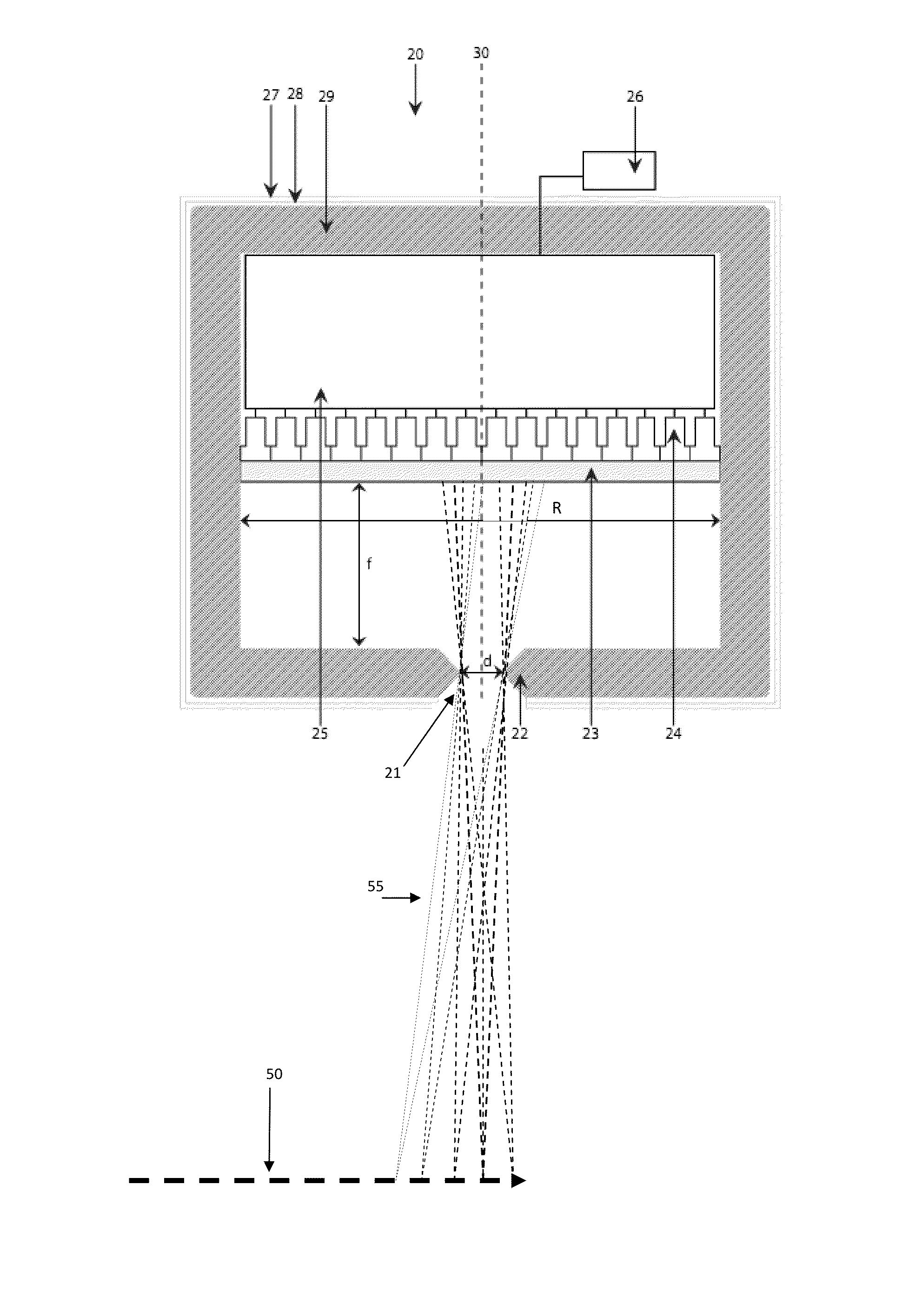
[0146]In another preferred embodiment a pinhole camera is used to detect the prompt gammas emitted from the irradiated body or object.

[0147]The camera is installed such that is optical axis (30) is perpendicular to the beam direction 50 in order to detect prompt gammas emitted from the object.

[0148]The pinhole gamma camera is equipped with shielding against neutrons, X-ray and unwanted gamma-rays.

[0149]As depicted in FIG. 5 the pinhole camera (20) is equipped with a pinhole collimator (21) made in a high atomic number material such as Pb or W.

[0150]An advantage of using a pin-hole camera when compared with an Anger camera is that a pin-hole camera can be better shielded for background irradiation.

[0151]A problem with the Anger camera is the fact that to obtain a high resolution when measuring the distribution of prompt gammas, the distance between the collimators is small (few mm, e.g. 2 or 3 mm) and hence the effective shielding is reduced.

[0152]Preferably, the section following an...


PUM


Abstract

The invention is related to the field of charged Hadron Therapy, i.e. radiation therapy using strongly interacting particles. More particularly, the invention relates to a detector and method for measuring the beam range of a charged hadron beam in a target object as well as the particle dose distribution in the target object.

Description

CROSS REFERENCE To RELATED APPLICATIONS[0001]This application is a national phase application of International Application No. PCT / EP2009 / 058458, filed Jul. 3, 2009, designating the United States and claiming priority to European Patent Application No. 08159577.9, filed Jul. 3, 2008, both of which are incorporated by reference herein in their entirety.FIELD OF THE INVENTION[0002]The invention is related to the field of charged Hadron Therapy, i.e. radiation therapy using strongly interacting particles. More particularly, the invention is related to a detector and method for measuring the beam range of a charged hadron beam in a target object as well as the particle dose distribution in the target object.STATE OF THE ART[0003]It is well established that charged hadrons (i.e., protons, pions, ions such as carbon ions) have physical advantages with respect to X-rays or gamma rays in the field of radiation therapy. For example, protons of a given energy (i.e. forming a mono-energetic pr...

Claims


Application Information

Patent Timeline
Patent Type & Authority Patents(United States)
IPC IPC(8): G21K1/02
CPCA61N5/1048G01T1/1642G01T1/169A61N2005/1052A61B6/4258A61N2005/1087
Inventor JONGEN, YVESSTICHELBAUT, FREDERIC
Owner ION BEAM APPL
Learn More