
Joint product between steel product and aluminum material, spot welding method for the joint product, and electrode chip for use in the joint product

a technology for aluminum products and joint products, which is applied in the direction of manufacturing tools, transportation and packaging, other manufacturing equipment/tools, etc., can solve the problems of high welding cost, difficult to obtain a reliably high strength joint part, and increase the welding cost, so as to reduce the cost, enhance the bonding strength of the dissimilar material joint product, and achieve the effect of high bonding strength

Active Publication Date: 2013-07-16
KOBE STEEL LTD
View PDF43 Cites 36 Cited by
  • Summary
  • Abstract
  • Description
  • Claims
  • Application Information

AI Technical Summary

Benefits of technology

The present invention relates to a method for joining steel and aluminum materials by spot welding, which can form a strong bond without the need for additional materials or steps. By controlling the area and thickness distribution of the interface reaction layer formed during the welding process, the method can enhance the bonding strength of the joint product. The invention can be applied to various structural members in vehicles, mechanical parts, building structures, etc. A suppression layer is used to control the interface reaction layer formation and prevent corrosion between the steel and aluminum materials. The suppression layer can be a metal film or an organic resin adhesive film, depending on the requirements of the joint. The invention allows for the efficient use of existing spot welding apparatus, reducing costs.

Problems solved by technology

However, in joining together a steel product and an aluminum materials a brittle intermetallic compound is readily produced at the joint part and it is very difficult to obtain a joint part having reliably high strength (bonding strength).
Accordingly, joining for such a dissimilar material joint product (joint product of dissimilar metal members) has been conventionally performed using a bolt, a rivet or the like, but this has a problem in the coupling joint reliability, airtightness, cost and the like.
However, all of these methods involve not a simple spot welding but a spot welding in multiple layers, require a separate step such as plating or working, raise an issue that new equipment must be incorporated into the ousting welding line, or incur a rise of the welding cost.
Furthermore, these methods all have many problems in view of operation, such as severe limitations on the welding conditions.
However, in Patent Document 8, the strength is 80 kgf and is insufficient, though the breaking is a base material rupture.
Merely by an anchor effect owing to such microscopic bonding, tensile shear strength may be ensured but cross tensile strength (peel strength) cannot be maintained, and the usage is limited to special cases involving only tensile shear stress.
In Patent Document 10, a resistive element needs to be further inserted and this not only raises the above-described issue that new equipment must be incorporated into the existing welding line, but also incurs a rise in the cost.
Certainly, the interface reaction layer which is an intermetallic compound of steel and aluminum is brittle, but according to the present inventors, it is found that if the interface reaction layer is not present at all as in Patent Document 10, an adherence layer by interdiffusion is in turn not formed and low bonding strength results.
Accordingly, similarly to Patent Document 9, merely by microscopic bonding, sufficiently high cross tensile strength cannot be maintained, and the demand for a higher-strength joint product cannot be responded to.

Method used


Image

  • Joint product between steel product and aluminum material, spot welding method for the joint product, and electrode chip for use in the joint product
  • Joint product between steel product and aluminum material, spot welding method for the joint product, and electrode chip for use in the joint product
  • Joint product between steel product and aluminum material, spot welding method for the joint product, and electrode chip for use in the joint product

Examples


examples

[0425]

TABLE 9Component of Steel Product(mass %, balance: Fe)Kind of Steel ProductCSiMnPSHigh-tension steel of 270 MPa20ppm0.010.140.0160.008gradeHigh-tension steel of 590 MPa0.0670.011.800.0080.003gradeHigh-tension steel of 780 MPa0.110.012.010.0110.003gradeHigh-tension steel of 980 MPa0.130.012.300.0100.002grade

[0426]

TABLE 10Components of Compound (at %)Kind of CompoundFeAlZnAl5Fe2-Based compound24.0 to 29.070.0 to 74.0—Al3Fe-Based compound18.0 to 24.074.5 to 81.0—Fe3Zn7-Based compound31.0 to 40.0—60.0 to 69.0

[0427]

TABLE 11(High-Tension GA Steel Sheet of 980 MPa Grade)Spot Welding conditionsSheetWelding PressureWelding PressureSheetThickness(kN), Welding(kN), WeldingNumber ofThickness t1t2Current (kA) andCurrent (kA) andGalvanizationSteelof SteelofSheetWelding TimeWelding TimeTip DiameterFilm ThicknessProductsProductAluminumThickness(msec) in(msec) inof ElectrodeMark(μm)Stacked(mm)(mm)Ratio t1 / t2First Welding StepSecond Welding StepChipRemarks1none11.21.01.23 kN-24 kA-200 msec—150R...


PUM

PropertyMeasurementUnit
temperatureaaaaaaaaaa
diameteraaaaaaaaaa
diameteraaaaaaaaaa

Abstract

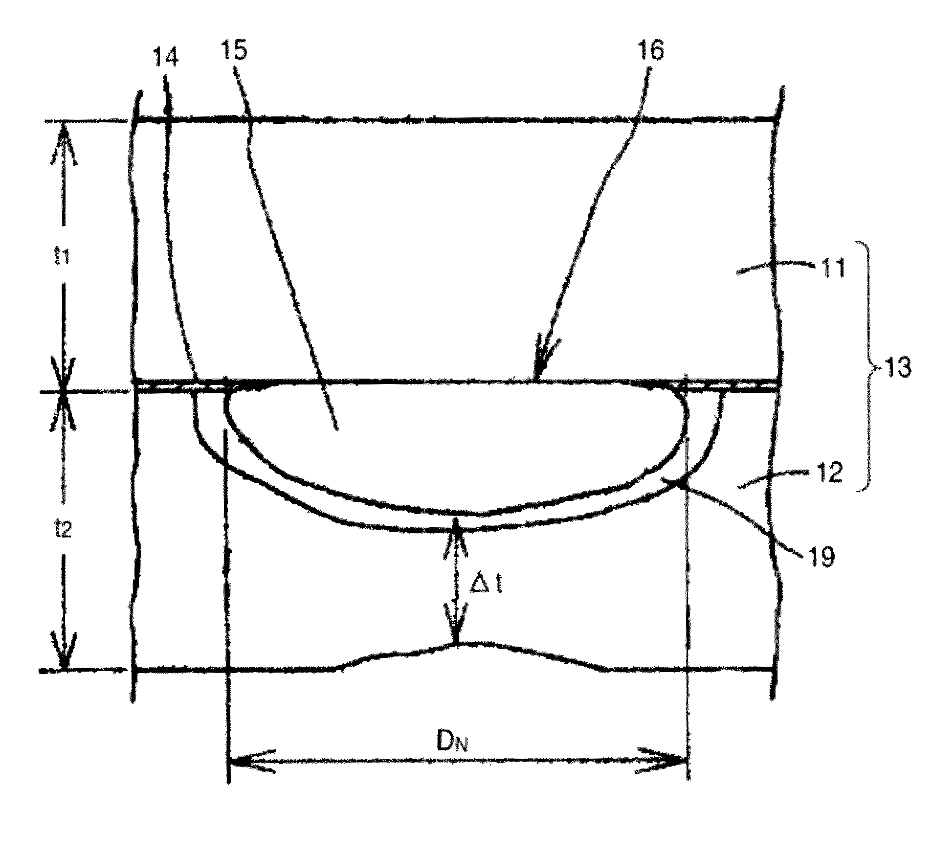
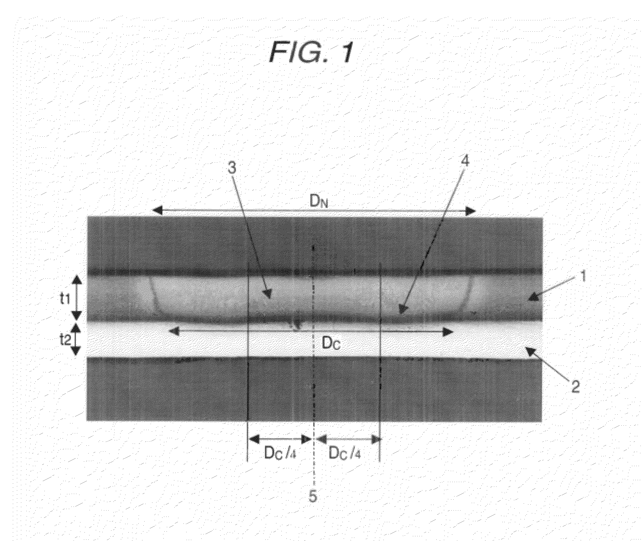
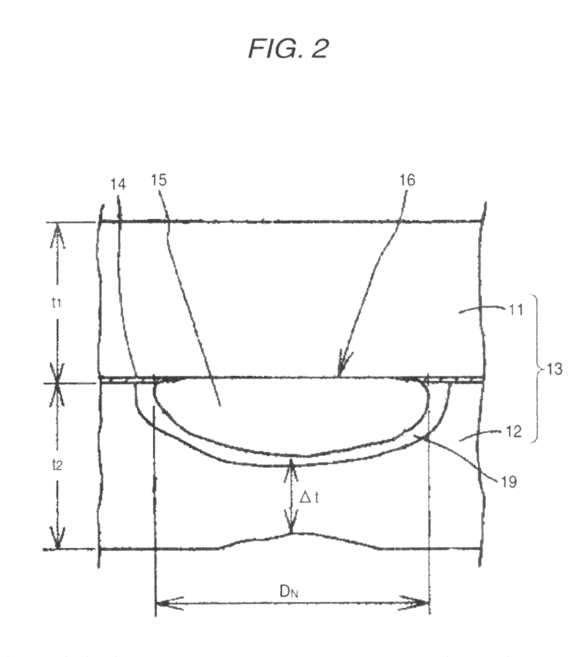
Provided is a joint product of a steel product and an aluminum material, the joint product being formed by joining the steel product having a sheet thickness t1 of 0.3 to 3.0 mm with the aluminum material having a sheet thickness t2 of 0.5 to 4.0 mm by spot welding, wherein a nugget area in a joint part is from 20×t20.5 to 100×t20.5 mm2, an area of a portion where a thickness of an interface reaction layer is from 0.5 to 3 μm is 10×t20.5 mm2 or more, and a difference between the thickness of the interface reaction layer at a joint part center and the thickness of the interface reaction layer at a point distant from the joint part center by a distance of one-fourth of a joint diameter is 5 μm or less, and wherein the aluminum material is pure aluminum or an aluminum alloy material.

Description

CROSS-REFERENCE TO RELATED APPLICATIONS[0001]The present application is a divisional of U.S. patent application 12 / 280,599, filed on Aug. 25, 2008, which is a 35 U.S.C. §371 National Stage patent application of International patent application PCT / JP2007 / 053228, filed on Feb. 21, 2007, which claims priority to Japanese patent applications JP 2006-313139, filed on Nov. 20, 2006, JP 2006-234054, filed on Aug. 30, 2006, JP 2006-056751, filed on Mar. 2, 2006, and JP 2006-047090, filed on Feb. 23, 2006.TECHNICAL FIELD[0002]The present invention relates to a technique of joining a steel product with an aluminum material by spot welding, which is required in the assembling process of a transit vehicle such as automobile and railway vehicle, a mechanical part, a building structure or the like.BACKGROUND ART[0003]Spot welding generally joins together similar metal members with each other. However, if it is applicable to joining of dissimilar metal members (dissimilar material joint product),...

Claims


Application Information

Patent Timeline
Patent Type & Authority Patents(United States)
IPC IPC(8): B23K11/11B23K11/20
CPCB23K11/115B23K11/20B23K11/3009C09J5/10B23K2201/006Y10T428/12347B23K2201/20B23K2203/20B23K2201/18B23K2101/006B23K2101/18B23K2101/20B23K2103/20B23K11/11B23K11/30
Inventor URUSHIHARA, WATARUTAKEDA, MIKAKOMATSUMOTO, KATSUSHIKATOH, JUN
Owner KOBE STEEL LTD
Learn More