Jet cavity catalytic heater

a heater and jet cavity technology, applied in the field of catalytic heating systems, can solve the problems of burner fatigue, heater rupture, fuel and air burning unsteady and explosively,

Active Publication Date: 2013-07-23
GHT GLOBAL HEATING TECH
View PDF11 Cites 2 Cited by
  • Summary
  • Abstract
  • Description
  • Claims
  • Application Information

AI Technical Summary

Benefits of technology

[0016]In the present invention, it has surprisingly been found there is a reduced cost and operational advantage to having a cavity within the porous catalyst bed, and that plasma forms within such cavity. The inter-diffusion of fuel and air through the porous catalytic bed achieves a high occupation time over the catalyst for molecules that is equal for all molecules present rather than the situation in forced flow through catalytic beds. In the latter, laminar flow, also known as “streamline flow” or “non-diffusionally driven,” mass flow through a random porous catalytic bed leads to non-uniformity of gas composition radially in the flow channels, and an uneven flow distribution such that larger channel flows dominate throughput, and flow rates therein can be high enough to prevent sufficient diffusion to the catalytic sites to catalytically react a portion of the fuel and air. Thus, some of the fuel air mixture can pass by the catalytic surfaces without interacting and produce incomplete combustion. Within the catalytic bed the inter-diffusion catalytic combustion can achieve a temperature gradient from highest on the interior cavity and then drops to the outside, important to achieving complete combustion. The present invention has found that if the outer surfaces of the catalytic bed are kept below 400° C. to 200° C. centigrade with a stoichiometric excess of oxygen to methanol fuel, and a rock wool / catalytic bed is uniformly catalytically active the unburned combustion products can drop below 1 part in 10,000 or the limits of our measuring equipment. By depending on this process of inter-diffusion through a separating catalytic bed wall, the new heater invention does not require fans or pumps. The new invention may use convection air flow and / or jets to admit fuel vapor or air in a distributed fashion, leading to a simple, quiet, clean burning and robust heater system. The hot catalytic surfaces which face the air flow also can fully oxidize and thereby eliminate gases in the air stream such as hydrocarbons and carbon monoxide as they flows through the heater. Additional devices that can be coupled with the heater air inlet are air filters, electrostatic air filters, photo catalytic air filters, absorbers, adsorbers, scrubbers, similar devices or, for the exhaust air, water condensers and / or carbon dioxide traps. Scents and perfume emitters arranged with the heater could be used, and some high molecular weight examples may pass through the heater unoxidized and so may be borne as an additive to the fuel. This heater system can also be used in conjunction with a membrane catalytic heater pending U.S. patent application Ser. No. 10 / 492,018, incorporated by reference.

Problems solved by technology

Conventional burners that mix fuel and air together for combustion within a cavity can lead to unsteady and explosive burns of the fuel and air.
This can lead to burner fatigue and disastrous results such as, for example, rupture of the heater.
It has been found that fuel air mixtures can vary in time which may lead to flame front loss and explosions when re-establishing the flame.
This is a particular problem in burning of tail gasses from refineries or catalytic reaction systems of two streams of reactants.
In the latter, laminar flow, also known as “streamline flow” or “non-diffusionally driven,” mass flow through a random porous catalytic bed leads to non-uniformity of gas composition radially in the flow channels, and an uneven flow distribution such that larger channel flows dominate throughput, and flow rates therein can be high enough to prevent sufficient diffusion to the catalytic sites to catalytically react a portion of the fuel and air.

Method used


Image

  • Jet cavity catalytic heater
  • Jet cavity catalytic heater
  • Jet cavity catalytic heater

Examples


Embodiment Construction

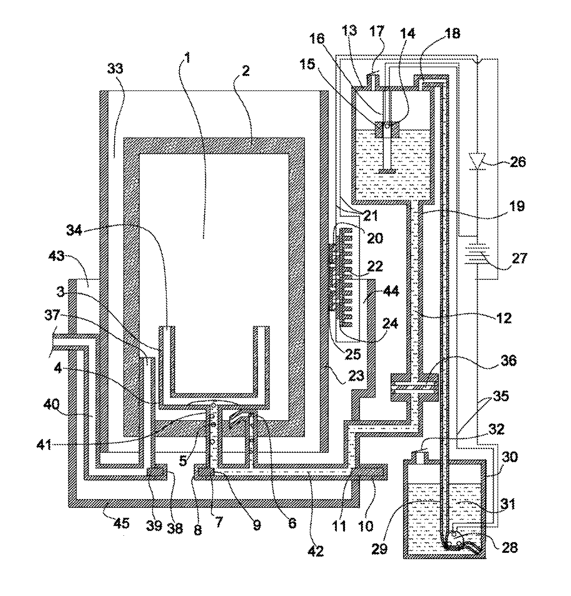
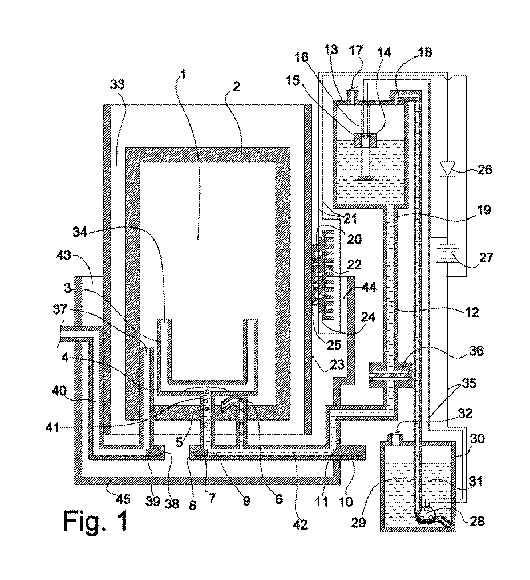
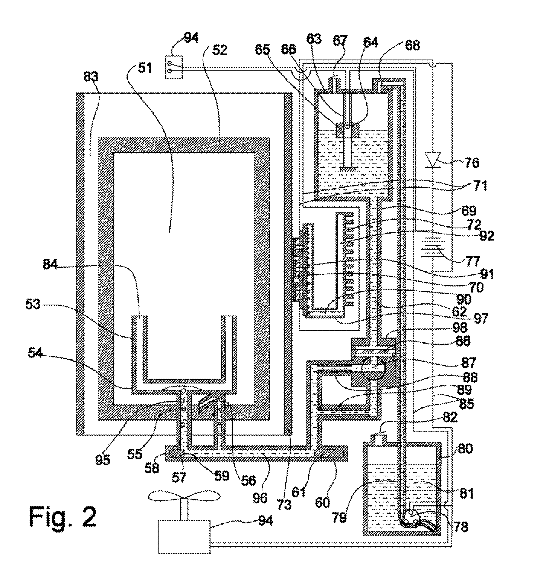
[0129]FIG. 1 is a cross sectional view of a jet cavity heater and fueling system according to an exemplary embodiment of the present invention. In this exemplary embodiment, the major components include a catalytic burner, a fuel distribution system, a flow control system, and a fuel tank system.

[0130]The illustrated catalytic burner has a catalytic bed 2 surrounding a catalytic bed cavity 1, and a chimney 23. The fuel distribution system is comprised of a porous tube 3, compression fittings 4, one or more small capillary tubes 6, and a gas inlet nozzle 37. The flow control system is comprised of a valve seal 9, a wax actuator and valve seat 11, and a fuel filter 36. The fuel tank system is illustrated as being comprised of a fuel line 12, a gravity feed tank 13, an inlet line 18, a peristaltic pump 28, and fuel tubing 29. There may also be one or more electrical wires 35 to the peristaltic pump 28, thermopile 20, and an electrical energy supply 27, preferably in the form of a recha...


PUM

PropertyMeasurementUnit
pore diameteraaaaaaaaaa
diameteraaaaaaaaaa
diameteraaaaaaaaaa

Abstract

The present invention is a method of delivering vaporized alcohol fuel through a thermally conductive porous nozzle to a catalytic burner with a plasma cavity and a surrounding porous catalytic cavity with fuel vapor and air supplied separately and inter diffusing into each other from different routes to the catalyst to achieve an efficient, steady, and complete combustion of the hydrogen bearing fuels. This heating system with passive auto thermostatic behavior, coupled to thermopiles, heat pipes and fluid heating systems may provide useful heat and electricity to applications of floors, roadways, runways, electronics, refrigerators, machinery, automobiles, structures, and fuel cells.

Description

CROSS-REFERENCE TO RELATED APPLICATION[0001]The present invention claims priority to provisional U.S. Patent Application No. 61 / 140,902 as filed on Dec. 26, 2008.STATEMENT REGARDING FEDERALLY SPONSORED RESEARCH[0002]Not applicable.NAMES OF THE PARTIES TO A JOINT RESEARCH AGREEMENT[0003]Not applicable.INCORPORATION-BY-REFERENCE OF MATERIAL SUBMITTED ON A COMPACT DISC[0004]Not applicable.BACKGROUND ON THE INVENTION[0005]1. Field of the Invention[0006]The present invention relates generally to heating systems, and more particularly to catalytic heating systems that generate heat and electricity via an oxidation reaction within a cavity having porous catalytic walls.[0007]2. Description of the Related Art[0008]The early inventions of liquid fueled heating systems include the oil lamp and the candle. Each early liquid fueled heating system wicks fuel up to a region where the fuel could evaporate and combust. Oils and kerosene lanterns can use the wick directly. Alcohol burners, and in pa...

Claims


Application Information

Patent Timeline
Patent Type & Authority Patents(United States)
IPC IPC(8): F24J1/00F24V30/00
CPCF23C13/00F23D3/08F23D3/10F23D3/22F23D5/126F23D3/40F23D2900/03081F23D2206/0063F23D2700/005F28D15/0275F23D2900/31004
Inventor VACCA, GIAMPAOLOPOSTON, JEFFREYSWANK, MICHAEL A.HOCKADAY, ROBERT GLENNWEBER, LAWRENCEBAGRIY, PAVLO
Owner GHT GLOBAL HEATING TECH
Why Eureka
Try Eureka